This company actually makes the Corvair wiring harnesses sold by Clark's Corvair Parts. Their Corvair catalog for 2023 is attached.
Here is the link to the Clark's Corvair Parts online catalog that covers wiring harnesses...66vairguy wrote: » Thu Sep 03, 2015 12:46 pm
I'm an electrical person and I just wanted to say I had a great experience with M&H Electrical Fabricators in the Los Angeles area...
...Clark's sells M&H wiring harnesses and as far as I can determine M&H is the ONLY supplier that makes ALL the Corvair harnesses, even the one wire with connectors for the Spyder/Corsa thermistor (drives the temperature gauge).
I stopped by M&H's place of business and they were very helpful (I'm modifying one of their harnesses) and knowledgeable. I've used their harnesses in both my cars and fit and function is excellent.
M&H makes harnesses for lots of cars, but there commitment to the Corvair is worth noting. There are other suppliers, but over the years I've seen a number of so called "Corvair" wire harnesses from other suppliers that were incorrect or badly assembled that caused owners problems.

Mailing Address:
M&H Electric Fabricators, Inc.
13537 Alondra Blvd.
Santa Fe Springs, CA 90670
e-Mail Address: sparky@wiringharness.com
Sales and Customer Service: (562) 926-9552
Technical Support: (562) 926-9562
24 Hour Fax Line: (562) 926-9572
The Corvair shop manuals divide the engine compartment, interior, and trunk wiring diagrams into separate sections that are displayed on separate pages. Sometimes it is easier to analyze a circuit if you can trace it end-to-end on the same page. Each schematic is displayed below first as an embedded image that can be enlarged by left-clicking it with your mouse for better viewing. If the cursor appears with a plus (+), the image can be clicked again to further enlarge it. The second image in each group is the same image, but displayed as a slightly larger "preview"...
- 1965 Corvair Corsa Full Schematic (Rev. E)
Left-click the image to enlarge it for better viewing or "Pan & Scan"...
- 1965 Corvair Monza Full Schematic (Rev. E)
There were several diagram errors in the 1965 shop manual that I have corrected. These errors were in the wiring of the left-rear tail light, the wiring of the tachometer sensing wire and the thermistor wire for the Corsa instrument panel connection, and a couple of wires on the Monza/500 instrument panel 12-pin multi-connector that were incorrectly positioned (instrument panel lamps and the high beam indicator).
Some of the labeling has been modified or enhanced to reflect "Corsa Only", Powerglide Only", "Manual Transmission Only", etc.
These two diagrams attempt to show the differences between the Corsa and the Monza (primarily the instrument clusters). Because of the difficulty in editing these images, I did not completely remove some of the "Corsa only" wiring between the engine and the instrument panel harness, but you will be able to see that the Monza connector simply omits the wiring that is unique to the Corsa, by leaving some of the pins in the 12-pin multi-connector empty.
**********************************************************************************************************************************************************************************


Left-click the image to enlarge it for better viewing or "Pan & Scan"...
- 1964 Combined Passenger Compartment & Engine Compartment Wiring Diagram
In the schematic diagram below I have combined the engine compartment, interior and trunk wiring diagrams for the 1964 Corvair passenger car into a single diagram.
Left-click the image to enlarge it for better viewing or "Pan & Scan"...
- 1964 Corvair Passenger Car Combined Schematic
In the schematic diagram below I have combined the engine compartment, interior and trunk wiring diagrams for the 1964 Corvair passenger car into a single diagram. I have also modified the wiring diagram to remove the generator and generator voltage regulator and replace them with the 1965-69 alternator and external alternator voltage regulator.
I used existing generator wiring to connect the alternator voltage regulator to the alternator and labeled the terminals. I added the wire labeled 10 R to the alternator connection and added a junction point to connect it to the existing wire labeled 10 R (routed from the battery positive terminal to the ten pin multi-connector). A voltage regulator voltage sensing wire labeled 20 R was also added from voltage regulator connector 3 to the existing positive battery wire 10 R (requires a splice connection). The existing wire labeled 20 BRN was retained and is connected to the voltage regulator connector 4. (This is the GEN/FAN warning light).
Left-click the image to enlarge it for better viewing or "Pan & Scan"...
- 1964 Corvair Passenger Car Combined Schematic (Alternator Mod)
**********************************************************************************************************************************************************************************


Left-click the image to enlarge it for better viewing or "Pan & Scan"...
- 1963 Corvair Passenger Car Combined Schematic
Left-click the image to enlarge it for better viewing or "Pan & Scan"...
- 1963 Passenger Car Combined Schematic (Alternator Mod)
**********************************************************************************************************************************************************************************

Left-click the image to enlarge it for better viewing or "Pan & Scan"...
- 1962 Combined Passenger Compartment & Engine Compartment Wiring Diagram
In the schematic diagram below I have combined the engine compartment and interior wiring diagrams for the 1962 Corvair passenger car into a single diagram. I have also modified the wiring diagram to remove the generator and generator voltage regulator and replace them with the 1965-69 alternator and external alternator voltage regulator.
I used existing generator wiring to connect the alternator voltage regulator to the alternator and labeled the terminals. I added the wire labeled 10 R to the alternator connection and added a junction point to connect it to the existing wire labeled 10 B (routed from the battery positive terminal to the eight pin multi-connector). A voltage regulator voltage sensing wire labeled 20 R was also added from voltage regulator connector 3 to the existing positive battery wire 10 B (requires a splice connection). The existing wire labeled 20 BRN was retained and is connected to the voltage regulator connector 4. (This is the GEN/FAN warning light).
Left-click the schematic diagram below to enlarge for better viewing…
- 1962 Combined Passenger Compartment & Engine Compartment (Alternator Mod)
Left-click the schematic diagram below to enlarge for better viewing…
- 1962 Passenger Car Combined Schematic
Left-click the image to enlarge it for better viewing or "Pan & Scan"...
- 1962 Passenger Car Combined Schematic (Alternator Mod)

Left-click the image to enlarge it for better viewing or "Pan & Scan"...
- 1962 Corvair 95 Full Schematic (Corrected)
- 1964 Combined Passenger Compartment & Engine Compartment Wiring Diagram
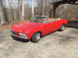
 1966 Corvair Corsa Convertible