The ignition coil positive terminal on the Corvair receives power from two sources. The first source is the ignition switch when it is in the ON position. Turning the key ON provides switched power to a number of circuits in the car. If you locate the ignition switch in the bottom diagram below (near the top-center portion of the schematic diagram) you will see that it has three terminals, labeled "C", "S" and "R".
"R" - Receives 12 VDC from the battery power source at all times. You will see the wire connected to a wiring junction that powers the horn relay, the main light switch, the dome lamp circuit, the cigarette lighter, and the ignition switch.
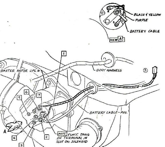
"S" - Sends power to the starter solenoid to engage the starter whenever the key is turned to START.
"C" - Sends switched power to another wire junction that is only powered when the key is in the ON position. This powers things like the PRES/TEMP and GEN/FAN warning lights, the Gas Gauge, and the ignition coil.
If the key is ON, and you see the instrument panel warning lights illuminated, then you know that power is being fed from the ignition switch to the junction that powers both the warning lights AND the coil. If the instrument panel warning lights are on, but you can measure no voltage between the coil positive terminal and Ground, you should first suspect the 8-pin multi-connector in the engine compartment. With the key ON, power enters the 8-pin multi-connector via the 18 BRN (18 gauge Brown) wire. On the other side of the connector, the voltage is fed through a special ballast resistor wire labeled 20 W/OR/PPL that reduces the voltage from 12 VDC to approximately 7 VDC. After passing through the resistor wire, the voltage passes across a 2 pin multi-connector coming from the starter solenoid (labeled 20 Y - 20 gauge yellow). The 20Y wire then continues on to the ignition coil positive terminal.
The 8-pin multi-connector is often a source of trouble. As it ages, gets wet and dirty, is subjected to vibration and heat, etc. the eight metal pins inside the plastic housing can be come bent, loose, or corroded. You should separate the two halves and check for voltage at the 18 BRN wire when the key is on. If the metal pins are not making good contact, the voltage coming from the firewall side and instrument panel may not be getting through to the other side. You can inspect and clean the two sides of the connector to try to restore the power connection if this connector is determined to be the trouble area. If power is getting through the connector, continue to check for electrical continuity through the resistor wire, and on to the coil to determine where the power is being interrupted.
The other source of power to the coil is from the starter solenoid "R" terminal. When the ignition key is turned to START, power is applied to the thick 12V (12 gauge Violet) wire that is connected to the "S" terminal on the solenoid. This energizes the solenoid, to engage the starter gear and to apply battery power to the starter motor. At the same time, a full 12 VDC is applied from the solenoid via the "R" terminal and yellow wire to the coil. The higher 12 VDC temporarily overrides the lower 7 VDC fed to the coil via the resistor wire. This higher voltage increases the spark voltage coming from the coil to the spark plugs, which enhances engine starting. As soon as the engine starts and the operator releases the ignition key, the higher voltage is switched off, leaving only the lower 7 VDC coming through the resistor wire. Using lower voltage during normal engine operation lowers the current through the ignition points, which reduces arcing and burning of the points and prolongs their operational life. Consequently the spark voltage output of the coil is also reduced, but it is still considered adequate for normal engine operation once it has started.
If you only hear the engine fire while the key is held to START, but the engine dies when you release the key and the starter solenoid disengages, the operating voltage from the ignition switch is probably not making it from the switch to the coil. If the warning lights come on with the key ON, but the coil receives no power, the multi-connector or the resistor wire may be suspect.
NOTE: The illustration showing the starter and harness is from a 1965 diagram so the wire color codes are slightly different than the actual 1963 configuration.