


Welcome to the Corvair Forum!
Many older vehicles have resistor wires feeding power to the coil when the engine is running. The resistor wires are bypassed when the engine is being started and full battery voltage is fed to the coil to facilitate start-up.
These wires were intended to reduce the voltage to the coil once the engine was running in order to extend the life of points. Most of the time an Pertronix Ignitor will work well with the resistor wire left in the circuit. However, in some cases the resistor wire, or its connections, may have deteriorated over time resulting in an excessive voltage drop at the coil.
If you study the wiring diagrams and illustrations below, you will see that the 20 B/Y wire that comes from the standard starter solenoid is spliced to a 20 W/R/B resistor wire that comes from the 12-pin multi-connector on the main engine compartment wiring harness. When the ignition switch is turned all the way to START, 12V DC is applied to the 12 PPL wire on the solenoid, which energizes the solenoid and engages the starter, cranking the engine. While the engine is cranking, 12V DC is applied to the 20 B/Y wire coming out of the solenoid, which temporarily provides a full 12V DC to the ignition coil. This is intended to increase the spark voltage from the coil, but only during the period that the engine is being cranked. This "hotter" spark makes it easier to start the engine. When the key is released, the voltage coming from the solenoid to the the coil is discontinued, which leaves only the lower voltage coming from the 20 W/R/B resistor wire (always present with the ignition switch key ON). The voltage through this resistor wire is reduced to approximately 7V DC. The purpose of reducing to this lower voltage is to extend the life of the stock ignition points, by reducing the operating voltage across the points during engine operation.
The red wire going to the Ignitor II module in the distributor requires a full 12V DC, as shown in the last illustration from the Ignitor instruction sheet. If the 20 B/Y wire from the starter solenoid is left disconnected, the voltage at the (+) terminal of the coil will always be at the lower 7V DC level, even during engine cranking.
You did not mention which ignition coil you are using with the Ignitor II. A standard or Flame Thrower coil has about 3 ohms primary internal resistance, but a Flame Thrower II coil has only 0.6 ohms internal resistance. With a full 12V DC source voltage and no resistor wire in the circuit (as you described earlier), and with only 0.6 ohms coil resistance you would have about 20 amps circuit current, and this may be the reason your ignition wire overheated and melted. (12V DC through 3 ohms coil resistance would produce only about 4 amps of current flow). The low resistance of the Flamethrower II coil coupled with a straight power wire with no resistor wire reducing the source voltage and resulting current might have overheated the circuit with too much current flow. With the resistor wire in the circuit, the current flow through the coil would be reduced, which should reduce potential heat in the primary ignition wire.
Without points, the lower ignition voltage needed to extend the life of the points is no longer an issue. If you are running a standard or Flamethrower coil with 3 ohms primary resistance, bypassing the resistor wire in the circuit would probably be OK and would give you a hotter spark to the spark plugs at all times. But I am not sure what is recommended if you are running a Flamethrower II coil with only 0.6 ohms internal resistance. Such a coil with the resistor wire in the harness bypassed might draw too much current and overheat the wiring harness.
Depending on the coil you are using, you might want to contact Pertronix tech support via the website or by phone, to ask them whether or not to bypass the wiring harness resistor wire in the circuit—especially if you are using the Flamethrower II low resistance coil. The resistor wire can be bypassed by simply moving the 20 B/Y wire that used to be connected to the starter solenoid to the other side of the resistor wire, picking up 12V DC at the 12 pin multi-connector 20 B/P wire, which provides a full 12V DC before it reaches the resistor wire in the wiring harness.
PerTronix, Inc.
440 East Arrow Highway
San Dimas, CA 91773
Phone: (909) 547-9058
Fax: (909) 599-6424
 http://www.pertronix.com/default.aspx
According to the Pertronix website, the Ignitor II "Senses engine startup and increases dwell time, providing more energy for starting sparks." This may mean that a lower feed voltage to the coil (through the wiring harness resistor wire) at all times—even during engine cranking—may be OK and will provide adequate spark for starting. This reduced voltage may be desirable to limit current flow in the coil primary circuit. The Flamethrower II coil provides a hotter spark than a standard coil at all times because of the increased current with only 0.6 ohms internal resistance, even at only 7V DC input voltage.
Full normal circuit operation can be restored by adapting a Ford solenoid to your Corvair, in conjunction with the Clark's aftermarket starter, as shown at the end of this post.
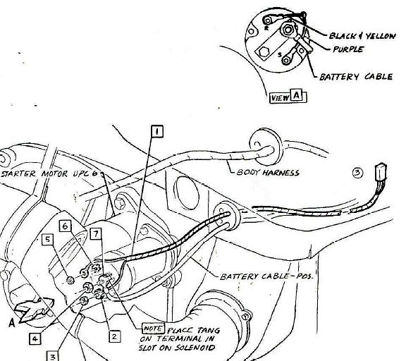
- 1965-1969 Corvair Engine Compartment Wiring Harness Starter Connections.jpg (80.88 KiB) Viewed 6033 times
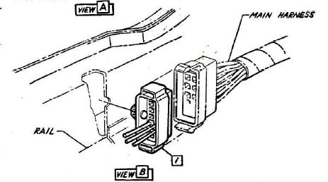
- 1965-1969 Corvair Engine Compartment Wiring Harness Multi-pin Connector.jpg (33.79 KiB) Viewed 6033 times
 Viewed 6033 times")
I did not realize the aftermarket starter sold by Clark's did not provide the switched 12V DC output provided by the standard starter solenoid when it is engaged. This would be a bigger problem with a car that still uses ignition points, since bypassing the resistor in the circuit would cause premature wear, burning and arcing of the points, and running without the solenoid circuit might produce an engine that is more-difficult to start with the resultant lower spark voltage while cranking the engine. A switching solenoid is needed to provide this function, and apparently Clark's has not considered this. I suppose a separate solenoid such as the one used in some Ford products could be adapted and substituted for this missing ignition system switching function when using the high-torque starter. Placing the Ford solenoid in the starter circuit, as shown, and connecting the 20 B/Y wire (that was originally connected to the stock starter solenoid "R" terminal) to the "I" terminal on the Ford solenoid would restore normal operation in the starter and ignition wiring.


Please let me know if you have any questions.


