Thanks Seth for the HEI history. Yes I remember the overheated coil packs in the distributor caps. Back in the day if you had an HEI acting up you looked to see if the laminated material was discolored from excess heat.
I had a 90 Corvette and not knowing any better at the time, I put in an "High Performance after market coil pack" for better performance according to the aftermarket hype. What a disaster that was. A lot of odd and intermittent problems. After market company "tech" service was clueless. I went back to all GM components and never had another ignition issue.
Melting wires, simple question
-
Frank DuVal

- Posts: 439
- Joined: Wed Dec 09, 2009 4:58 pm
Re: Melting wires, simple question
That's all Yes , Frank! What you said goes along with what I said. The bigger the gap the higher the voltage can rise before the spark shorts the circuit and reduces the voltage to zero. High voltage = corona, higher current, sparks going to the wrong paces, and other ills.  80 thousandths is really big! While it only takes ~2 kV to jump this gap in open air, with compression in the cylinder it takes a lot more. A whole lot more. Enough to exceed the insulation of the coil, etc.

Frank DuVal
Fredericksburg, VA
Hey look, blue background!


Fredericksburg, VA
Hey look, blue background!


Re: Melting wires, simple question
Four pages and 1100 views! This seemingly simple question isn't really all that simple, is it? While the OP is back in action, there's still no smoking gun/fault identified. Hopefully it was just something in the now replaced engine harness.
'61 140 PG Rampside
'66 Rear Alum V8 4-dr
'60 Monza PG coupe (sold, sniff, sniff)
'66 Corsa Fitch Sprint Conv. (First car 1971, recently repurchased)
'66 Rear Alum V8 4-dr
'60 Monza PG coupe (sold, sniff, sniff)
'66 Corsa Fitch Sprint Conv. (First car 1971, recently repurchased)
Re: Melting wires, simple question
Ok so I actually may have a reason why the harness melted or more specifically the brown wire but it also may be because of the recent aforementioned on the thread reason-just look at the monstrosity of an old harness that came out of the car.
But back to current status for now. The fan/Gen light is still shining bright. And the alternator is not charging as it is reading 12 to 12.2 on the voltmeter. So also is the main post on the alternator. Post #1 going to the fan/Gen light is showing 1 Volt. Post #2 is also at 12 to 12.2 volts at a consistent higher idle. However, the alternator rebuilder said the #2 Post should be going to the ignition, not strait to the battery. The only difference I can see in this is that it would only be charged when the car is in the on or running position. According to the mech he said the way it is is a drain. Ok that said the car always has started and runs even with the old melted harness!
So it is charging a bit? Why is that light on?
He's gonna fix the alternator.
- Attachments
-
-
Re: Melting wires, simple question
When running, #1 should be at system voltage, meaning 13.something. #2 was wired battery direct by GM; the wire's purpose is to bring the actual battery voltage to the regulator without any voltage loss.
Here's the same thing direct from Delco-Remy:
“1” Terminal - Indicator lamp/Ignition terminal carries full system voltage and connects to an indicator light or ignition terminal.
“2” Terminal - Voltage Sensing terminal monitors batteries system voltage at the Batteries or a common distribution point.
Since your alternator's #1 terminal isn't coming up to system voltage when the alternator is running, it's likely the alternator is broken. Slightly less possible: Your GEN/FAN light isn't providing enough current to start or "excite" the alternator and that would also cause no output. Has someone installed an LED GEN/FAN light bulb? An LED won't provide enough current to start the alternator.
'61 140 PG Rampside
'66 Rear Alum V8 4-dr
'60 Monza PG coupe (sold, sniff, sniff)
'66 Corsa Fitch Sprint Conv. (First car 1971, recently repurchased)
'66 Rear Alum V8 4-dr
'60 Monza PG coupe (sold, sniff, sniff)
'66 Corsa Fitch Sprint Conv. (First car 1971, recently repurchased)
Re: Melting wires, simple question
I find the coil discussion very interesting.
I dud replace the gen/fan bulb but I used the bulb kit from Clark's. Not understanding your last couple of lines completely I am now wondering if I used the correct bulb they provided.
I dud replace the gen/fan bulb but I used the bulb kit from Clark's. Not understanding your last couple of lines completely I am now wondering if I used the correct bulb they provided.
-
bbodie52

- Corvair of the Month

- Posts: 11937
- Joined: Mon Aug 06, 2012 12:33 pm
- Location: Lake Chatuge Hayesville, NC
- Contact:
Re: Melting wires, simple question
The above illustration from the 1965 Corvair Chassis Shop Manual, Page 6Y-5, illustrates what the external voltage regulator does. I believe you have a later model Delco alternator that utilizes an internal electronic voltage regulator module inside the alternator, but that internal voltage regulator basically has the same two functions provided in 1965 and later Corvairs that originally had external voltage regulators. The two voltage regulator functions are:
- Limits the alternator output voltage to a pre-set value (approximately 14.5 VDC) to power the vehicle electrical circuits and to charge the battery. It uses relays to control the alternator field current.
- The switch, resistor, and bulb depicted in the upper half of the diagram provides a warning bulb circuit (GEN/FAN) that illuminates the bulb whenever the key is in the ON position. This serves as a bulb test to confirm that the bulb has not failed. The ignition key applies voltage to one terminal on the bulb, and the resistor on the other side allows current to flow through the bulb filament as a bulb test. WHEN THE ENGINE IS STARTED AND THE ALTERNATOR BEGINS TO PRODUCE VOLTAGE OUTPUT TO THE VOLTAGE REGULATOR FIELD RELAY, THE FIELD RELAY CLOSES, APPLYING VOLTAGE TO THE BULB TERMINAL ON THE SIDE CONNECTED TO THE RESISTOR. This applies equal voltage to BOTH bulb terminals. With equal voltage applied to both bulb terminals, the voltage applied via the FIELD RELAY effectively cancels the bulb test illumination, and the bulb goes out. This tells the vehicle operator that the fan belt is intact and is spinning the alternator pulley, and that the alternator is providing output voltage and is charging the battery.
LEFT-CLICK THE SCHEMATIC DIAGRAM TO ENLARGE FOR BETTER VIEWING. CLICK A SECOND TIME FOR MAXIMUM ENLARGEMENT...
- 1964 Corvair Passenger Car Combined Schematic (Alternator Mod)
Alternator Conversion Kit, 1965 Corvair
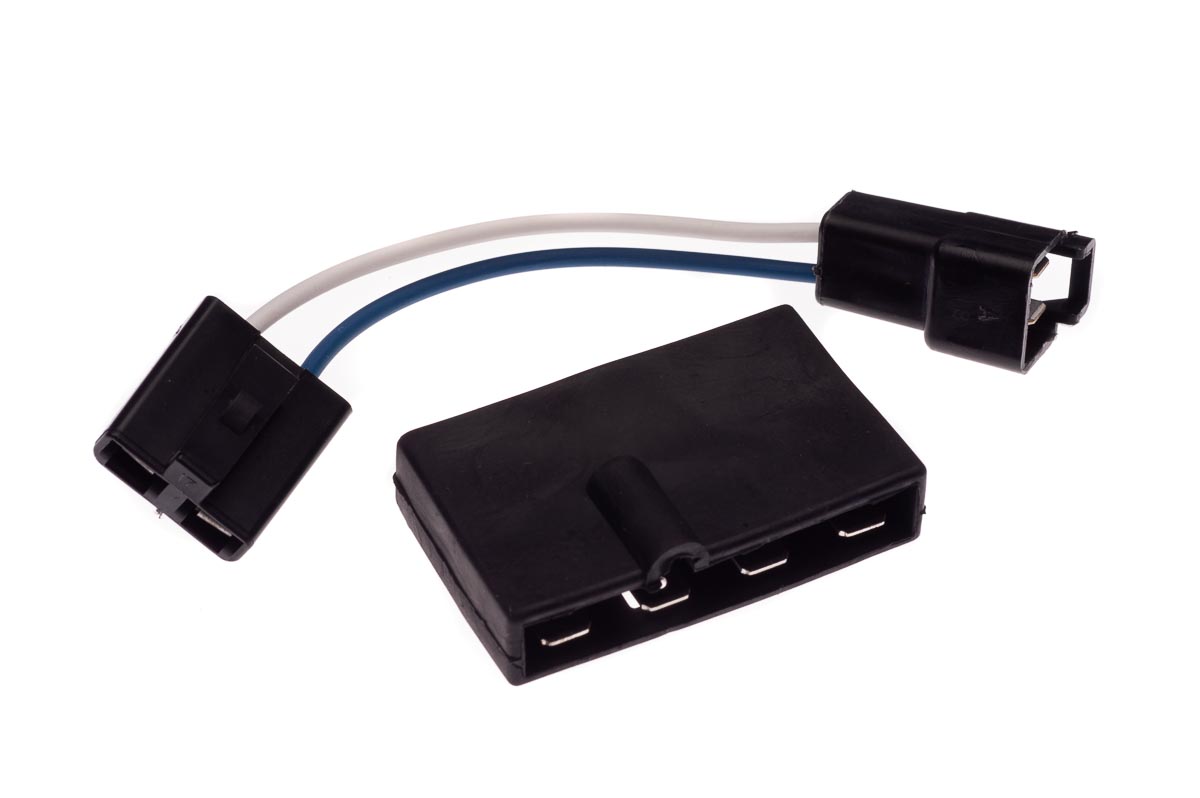
On your 1964 wiring harness, the wires are configured for connection to the original generator. You will have to locate the 20BRN wire that originally was intended to connect to a Generator-style voltage regulator ARM (Armature) terminal. This wire can be reconfigured to connect directly to the ALTERNATOR Field (F) terminal, which will provide a 12VDC output to the instrument panel GEN/FAN bulb to cancel bulb illumination when a voltage is present at the alternator F terminal.
- 1964 Corvair Passenger Car Combined Schematic
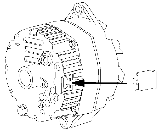
On the internally-regulated alternator, the alternator R terminal is connected to the battery Positive terminal wiring, as shown below...
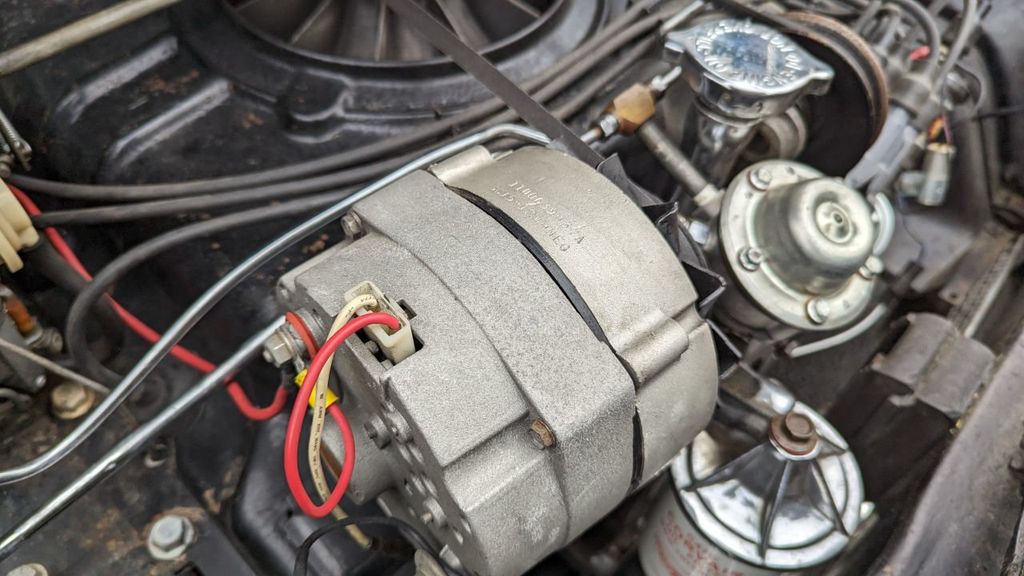
In this photograph, the white wire leaves the internally-regulated alternator terminal and ultimately sends voltage to the instrument panel GEN/FAN bulb, to cancel the bulb illumination when there is an output from the alternator. If the alternator were to fail, or the fan belt were to break, the voltage on the white wire would disappear and the instrument panel bulb would again illuminate to warn the driver.
The short red wire jumper from the alternator BAT terminal to the right-side alternator terminal provides the needed startup voltage to the alternator internal regulator circuitry.
Now that all of your problems have been solved...
- Attachments
-
- 1965 Corvair Chassis Shop Manual - SECTION 6Y - ENGINE ELECTRICAL.pdf
- 1965 Corvair Chassis Shop Manual - SECTION 6Y - ENGINE ELECTRICAL
- (8.51 MiB) Downloaded 2 times
Last edited by bbodie52 on Wed Apr 24, 2024 3:32 am, edited 1 time in total.
Brad Bodie
Lake Chatuge, North Carolina
 1966 Corvair Corsa Convertible
Lake Chatuge, North Carolina
1966 Corvair Corsa ConvertibleRe: Melting wires, simple question
Thanks Brad. Your writing is very articulate and understandable. And THAT is how we have it wired. The alternator is broke and being fixed.
Not to usurp everything but I checked my coil for Ohm resistance and you are correct it is not 0 resistance but it is at 1 Ohm.
The car runs good but I would like to revisit what happens at idle with this coil versus a 3 Ohm coil.
Also along with the harness I replaced the plugs and gaped them at .035. I also replaced the plug wires.
Remind you the alternator was bad
But
With three guys in the car it lugs at take off and pings. I think it should not do this.
When it gets fixed and installed will this be fixed?
Also will a change in coil make a difference in this take off situation with my powerglide?
I may have the idle set to low. I do have a high stall torque convertor. I wonder if I raise the idle if this will go away or maybe it was the alternator.
Re: Melting wires, simple question
I think it's worth mentioning that the plugs came out a little kean. I prefer a more rich condition. I tried to richen the carbs a little with the air mixure screws but the car ran bad so I returned it to a better idle. It may also be worth mentioning that the car has four primary carbs.
-
Frank DuVal
- Posts: 439
- Joined: Wed Dec 09, 2009 4:58 pm
Re: Melting wires, simple question
The external air adjustment screws on a Rochester H, HV are just to set idle mixture. So, just set for best idle!
Mixture at running speed/load is set by main jet size and float level.
Running premium for your area right? I hesitate to mention octane ratings, as they vary at pumps depending on altitude of the area they are in. Here it is 93 typically.
Does it ping right from a standing start, or when the Powerglide shifts?
Frank DuVal
Fredericksburg, VA
Hey look, blue background!
Fredericksburg, VA
Hey look, blue background!
-
bbodie52
- Corvair of the Month
- Posts: 11937
- Joined: Mon Aug 06, 2012 12:33 pm
- Location: Lake Chatuge Hayesville, NC
- Contact:
Re: Melting wires, simple question
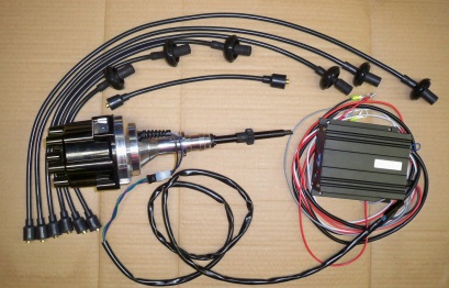
In rereading your initial posts, and the information about your engine pinging and the wiring harness issues, I suspect that you are way over your head with this Stinger racing distributor. That Stinger distributor appears to be anything but simple! The tunable, adjustable timing curve may be very incorrect for your engine, Powerglide transmission? Four Primary carburetors?NMVair wrote:I have a 1964 Monza with a 1968 140hp engine with a simple electronic ignition. The wires are severely melting or have melted, i.e. the wiring harness got hot, there's a short, and the insulation is melting. In fact they are still getting hot. I still have to trace down the problem.
There appears to be a lot of room for errors in properly setting up your engine. It sounds like it is far from stock, with possibly a lean fuel/air mixture and a timing curve that may simply be incompatible with an automatic transmission-based air cooled experimental racing engine. Your ignition system and fuel system likely needs a dose of detuning for use in a street configuration. If the engine is pinging due to detonation, the problems need to be resolved before mechanical damage occurs in one or more cylinders. Substituting a stock distributor and stock coil, and possibly disconnecting the two "secondary" carburetors may bring you back to some degree of normal compatibility for a Powerglide-based street Corvair.
Seth Emerson of Performance Corvairs markets these distributors. and has a lot of experience that may help you in analyzing what is going on with your engine configuration, to help you to find a way to match the engine tuning to your intended uses for that Corvair.sethracer wrote: » Tue Apr 16, 2024 12:45 pm
For reference. With the TSP distributor, I recommend bypassing the stock resistance wire and feeding both the coil and the distributor full battery voltage. I also recommend using ONLY a 3.0 Ohm coil with that set-up. With a battery voltage feed, you will still have plenty of spark output, and you will not be overstressing the internal electronics of the dist. I agree with BBodies52 comments.
All-new racing distributor for the Corvair motor.
Magnetic-pulse pickup triggers your choice of external electronics box (Like MSD-6, TSP (shown) or Intellitronix).Has adjustable mechanical advance. (Vacuum is an option). Mechanical advance can be locked out, if desired. Will act as crank or cam positional sensor for EFI systems. Vacuum block-off plate is installed for competition. Uses easily available GM parts and aftermarket accessories. Optional cap designs and colors for HEI cap or OEM style well-type cap. (shown) Cap clears top shroud and fan belt pulleys. No pressure retard is available at this time.

Contact Us:
Performance Corvairs
Seth Emerson
3462 Kirkwood Dr.
San Jose, CA 95117
Email: Sethracer@aol.com
Phone: (408) 247-2237
The chart below shows the GM timing curves and settings for a variety of engines, including the 140hp engine with manual transmission and with a Powerglide.
Some advanced timing lights, like the Innova unit below, have features that will help you to determine the amount of timing advance being dialed-in ad different engine speeds. Switching to a stock distributor, or adjusting the Stinger distributor timing curve may help you to find settings that will work with your engine.
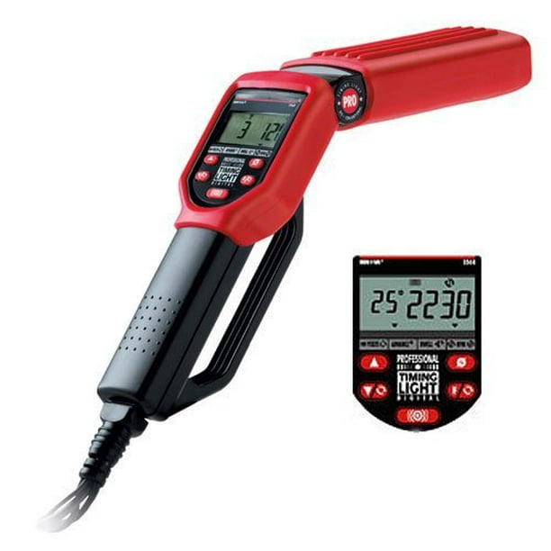
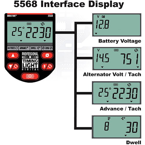
Now this is my weapon of choice! The Innova 5568 professional timing light includes four advanced function digital readouts utilizing an easy-to-read backlit LCD. Built for one-hand use, the 5568 maximizes vehicle analysis efficiency and durability.
The Innova 5568 Pro Digital Timing Light is made from a heavy-duty, ABS, shock proof housing encased by a molded boot for extra protection against the engine fan blades and accidental drops. It features a backlit screen for easier viewing in hard to see places. The four function digital readout displays tachometer ranges from 249-9,990 RPM, Advance Degrees (2 and 4 cycle) 0-90 degrees, dwell (2-12 cylinders) from 0-180 degrees and voltage from 10-16 volts DC.
INNOVA 5568 Pro Digital Timing Light with Storage Case


The newer lights also measure your rpm's and make it easier to set up your complete advance curve just in case you install a new distributor/a new vacuum cannister/new weights and springs etc.
Brad Bodie
Lake Chatuge, North Carolina
1966 Corvair Corsa Convertible
Lake Chatuge, North Carolina
1966 Corvair Corsa ConvertibleRe: Melting wires, simple question
Well, we will get the alternator back and see where we are.
I sontcfeel over my head but that us subjective I guess. I am just interested in how different couls affect idle.
I sontcfeel over my head but that us subjective I guess. I am just interested in how different couls affect idle.
Re: Melting wires, simple question
The pinging was only from take off with three guys in the car.
-
joelsplace
- Posts: 2030
- Joined: Wed Oct 13, 2010 12:51 pm
- Location: Northlake, TX
Re: Melting wires, simple question
A coil either fires the plugs or it doesn't. If it has the correct signal and power and doesn't fire the plugs the coil is bad. A coil won't change the idle.
The ping is either lean, too much advance, bad/low octane fuel, overheating or a combination of these.
The ping is either lean, too much advance, bad/low octane fuel, overheating or a combination of these.
157 Corvairs, 5 Ultravans and counting
Northlake, TX
Northlake, TX
Re: Melting wires, simple question
Someone, WAS talking about a miss at idle with a powerglide. I just know it. I know what your saying though.
-
RexJohnson
- Posts: 103
- Joined: Sun Feb 04, 2024 10:53 am
Re: Melting wires, simple question
The miss at idle is with the Pertronics II.
RJ Tools Salem, OR
69 conv pulling a 66 trailer
69 conv pulling a 66 trailer