Flame Thrower ignition coil
Flame Thrower ignition coil
My 66 140hp 4-sp. has a Flame Thrower ignition system with a 1 1/2 ohm coil, part# 40011. Flame Thrower charts tells me this is the wrong coil for a 6-cly. I have a new 3 ohm Flame Thrower coil, part# 40511 that I can install. So much confusion on the forum as to which coil I should use. Seems from what I read, that if there is a certain ballast present, the 1 1/2 ohm is fine????? Which coil should I use?
Gary Roberson
66 Vert 140 4-sp Corsa “clone”
66 Vert 140 4-sp Corsa “clone”
- bbodie52
- Corvair of the Month

- Posts: 12137
- Joined: Mon Aug 06, 2012 12:33 pm
- Location: Lake Chatuge Hayesville, NC
- Contact:
Re: Flame Thrower ignition coil
The 3 ohm Pertronix FlameThrower (40511) coil will work fine if you bypass the resistor wire in the wiring harness, allowing full battery voltage to be delivered to the coil positive terminal. The internal 3.0 ohm primary resistance will lower the current flow to an appropriate level to deliver the desired secondary voltage to the spark plugs, while maintaining a desired heat range buildup within the coil. If you don't bypass the ballast resistor wire, the voltage delivered to the coil will be somewhat low, at approximately 7 VDC, which will not harm the coil but will reduce the secondary voltage to the spark plugs. The reason, I believe, that Pertronix engineers recommend a 3.0 ohm coil is to simplify providing the desired 12 VDC to the electronic ignition module in the distributor (assuming you are using a Pertronix Ignitor I or Ignitor II breakerless ignition module in the distributor, to eliminate the use of ignition points). The Ignitor electronic circuitry is designed to be powered by a nominal 12 VDC battery voltage, which has to come either from tapping into th ignition key circuit BEFORE the resistor wire, or by bypassing the resistor wire to provide full voltage to the coil. (If you have full 12 VDC voltage at the col positive terminal, you can tap off of that connection to power the Pertronix Ignitor module inside the distributor).


Your original 1.5 ohm FlameThrower coil (40011) can also work, but with a six cylinder engine it might run hot and have a reduced operating life if the ballast resistor wire is bypassed, feeding it a full 12 VDC. It will run cooler with the external ballast resistor in the circuit, but if you were to retain the resistor wire in the circuit, you would have to run a separate power wire for the Pertronix Ignitor module to bypass the resistor wire while giving the Ignitor electronic module full 12 VDC power. (The shorter duty cycle switching the coil on and off with a V8 engine applies voltage for shorter periods during each engine revolution, which helps the 1.5 ohm coil to run cooler with a V8. The 4 and 6 cylinder engines have a longer duty cycle, leaving the coil primary ON for longer time periods during each engine revolution, so Pertronix recommends a 3.0 ohm coil to reduce coil heat buildup on a 6 cylinder engine when powered by full 12 VDC to the coil).
 I know all of this might give you headache, but they are the technical reasons for the different coil recommendations.
Your original 1.5 ohm FlameThrower coil (40011) can also work, but with a six cylinder engine it might run hot and have a reduced operating life if the ballast resistor wire is bypassed, feeding it a full 12 VDC. It will run cooler with the external ballast resistor in the circuit, but if you were to retain the resistor wire in the circuit, you would have to run a separate power wire for the Pertronix Ignitor module to bypass the resistor wire while giving the Ignitor electronic module full 12 VDC power. (The shorter duty cycle switching the coil on and off with a V8 engine applies voltage for shorter periods during each engine revolution, which helps the 1.5 ohm coil to run cooler with a V8. The 4 and 6 cylinder engines have a longer duty cycle, leaving the coil primary ON for longer time periods during each engine revolution, so Pertronix recommends a 3.0 ohm coil to reduce coil heat buildup on a 6 cylinder engine when powered by full 12 VDC to the coil).
Brad Bodie
Lake Chatuge, North Carolina
 1966 Corvair Corsa Convertible
Lake Chatuge, North Carolina
 1966 Corvair Corsa Convertible
Re: Flame Thrower ignition coil
Headache, that’s an understatement! The car came with the Flame Thrower ignition and has run just fine for the two years I’ve had the car with the 1 1/2 ohm coil. The only problem has been that the distributor rotor failed where the metal contact either broke off or burnt off. I have no idea if I have a ballast resistor or whether or not it’s been bypassed if indeed it has one. How can I tell? I would like to know if I should leave the 1 1/2 ohm coil in place or switch to the 3 ohm???
Gary Roberson
66 Vert 140 4-sp Corsa “clone”
66 Vert 140 4-sp Corsa “clone”
Re: Flame Thrower ignition coil
Brad, I checked the voltage at the positive terminal of the coil with the ignition switch in the on position and got 12.3 bolts. That means there is no ballast resistance wire in place and I need to install the 3 ohm coil, right?
Gary Roberson
66 Vert 140 4-sp Corsa “clone”
66 Vert 140 4-sp Corsa “clone”
Re: Flame Thrower ignition coil
Is it possible to post a picture of the wires on the coil? It could be helpful to answer your question.
Steve
Bakersfield,CA
1969 monza coupe
110, 4speed
Bakersfield,CA
1969 monza coupe
110, 4speed
- bbodie52
- Corvair of the Month

- Posts: 12137
- Joined: Mon Aug 06, 2012 12:33 pm
- Location: Lake Chatuge Hayesville, NC
- Contact:
Re: Flame Thrower ignition coil
In order to test for the presence or absence of a ballast resistor or resistor wire in the circuit, it is necessary to have an active circuit that includes the ignition coil. (The coil must be grounded at the negative terminal and ignition switch must be on).
CHECKING VOLTAGE:
BE SURE TO TURN THE IGNITION KEY OFF AND DISCONNECT THE TEMPORARY GROUNDING WIRE THAT WAS ATTACHED FOR THIS TEST TO THE COIL NEGATIVE TERMINAL. DO NOT LEAVE THE IGNITION SWITCH ON FOR A PERIOD OF TIME LONGER THAN NECESSARY TO TAKE THE VOLTAGE MEASUREMENT.
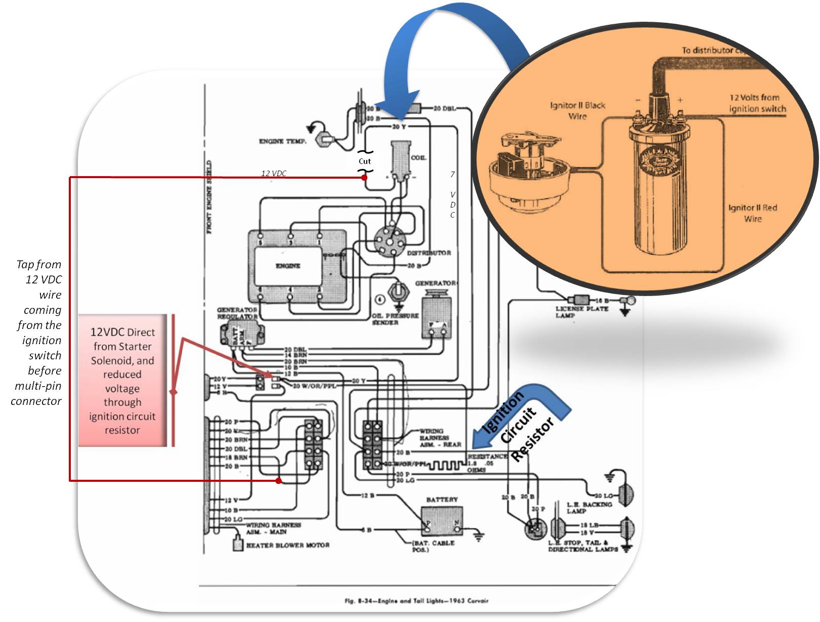
The resistor wire in the wiring harness is shown in the engine compartment wiring schematic diagram below. You can locate this wire by starting at the ignition coil positive terminal in the diagram. Trace the wire from the positive terminal backward to a two pin connector that attaches to the starter solenoid. The wire is labeled 20 B/Y (20gauge black/yellow). This wire is spliced to a resistor wire at the two pin connector, and continues on to a 12 pin multi-connector that is located below the voltage regulator on the left side of the engine compartment. That special resistor wire is labeled 20 W/R/B. This wire is rated at 1.8 ohms resistance. On the other side of the 12 pin multi-connector, the wire changes color and is labeled 18 P. This wire continues to the dashboard and is connected to the ignition switch. So the ignition coil power begins at the switch in the dashboard and is routed via the 18 P wire to the multi-connector, where it transitions into the special ballast resistor wire, that is wired to the two pin connector that attaches to the starter solenoid. The circuit continues on from that point to the ignition coil positive terminal as a 20 B/Y wire.
The spliced connection at the starter solenoid allows full battery voltage to be applied to the coil positive terminal from the starter solenoid when the engine is being started. The extra voltage to the coil is only applied while the engine is being cranked. This temporarily boosts the coil output voltage to the spark plugs to promote easier starting when cranking the engine. Once the engine starts, the driver releases the key and the solenoid is disengaged. This leaves only the ignition switch voltage that is reduced via the special ballast resistor wire to approximately 7 V DC. The lower voltage was intended to reduce heat buildup within the coil and also to reduce current through the ignition points, to extend the operational life of the ignition points contacts.
The above test will simulate closed ignition points for the purpose of measuring the voltage being applied with the key in the ON position. With the coil grounded at the negative terminal, the multimeter will measure the voltage being applied to the coil positive terminal. If a ballast resistor is present in the circuit, the voltage will be reduced to approximately 7 V DC. If the ballast resistor wire has been removed or bypassed, the voltage will read battery voltage, which should be approximately 12.5 V DC.
With the removal of the ignition points and the substitution of a breakerless ignition system, such as a Pertronix Ignitor or Ignitor II electronic switching module, the need for reduced voltage to prolong the life of ignition points is no longer necessary. However, it is desirable to continue to reduce the current flow through the ignition coil using a total of approximately 3 ohms of resistance in the circuit. This can be provided to the coil by the combination of an external ballast resistor wire plus a 1.5 ohm ignition coil. The two together add up to approximately 3 ohms, which is correct for the circuit. If the ballast resistor wire is has been bypassed or removed, the coil itself can provide the entire 3 ohms of resistance by installing and ignition coil with a 3 ohm primary in the design. Either way, the final outcome that is desired is to provide reduced current through the coil while still providing full battery voltage (12.5 V DC) to the Pertronix module inside the distributor. That way the Pertronix Ignitor receives its desired 12.5 V DC, while the coil happily operates with reduce current by total of 3 ohms in its primary circuit. You do not want to use a 3 ohm coil in conjunction with an external ballast resistor, because the total resistance would be approximately 4.8 ohms, which would reduce the output voltage to the spark plugs significantly and weaken the coil output to the spark plugs.
I hope that this explanation help you to visualize the changes needed to the factory ignition circuit to accommodate the use of the Pertronix Ignitor breakerless electronic ignition system.
The diagrams below show the engine compartment wiring and the suggested Pertronix wiring options to apply correct voltage to both the coil and the Pertronix Ignitor ignition module.


FIGURE 1 – Original Chevrolet ignition wiring.
FIGURE 2 – Wiring suggestion for the Pertronix Ignitor connected to a 3 ohm ignition coil.
FIGURE 3 – Wiring suggestion for the Pertronix Ignitor connected to a 1.5 ohm ignition coil plus retaining an external ballast resistor wire, for a total of 3 ohms resistance for the coil circuit while providing full 12.5 V DC to the Pertronix Ignitor module.

CHECKING VOLTAGE:
- Turn the engine off and make sure the key is in the OFF position.
- Attach a 20 gauge or larger (thicker) jumper wire between the coil negative terminal and a clean verified engine ground. (This simulates ignition points CLOSED – grounding the ignition coil negative terminal).
- Using a Digital Volt Ohm Meter (DVOM, or Multimeter), set the meter to the 20 V DC scale. (Meter set to read a voltage between zero and 20 V DC).
- Attach the red lead of the meter to the positive terminal of the coil.
- Attach the black lead of the meter to a good clean engine ground. (This is necessary to measure the voltage at the positive coil terminal).
- Briefly turn the key to the ON position without cranking the engine and observe the meter reading. Do not leave the key in the ON position more than a few seconds or damage can be done to the module and coil. (This applies voltage to the coil positive terminal from the ignition switch, with electrical current flowing through the coil to ground via the temporary coil grounding wire).
- Readings between 12.4 and 10 V indicate sufficient voltage for proper ignition function. Reading less than 10 V could indicate the presence of a resistor wire, ballast resistor, for engine ground or corroded wires and connections.
BE SURE TO TURN THE IGNITION KEY OFF AND DISCONNECT THE TEMPORARY GROUNDING WIRE THAT WAS ATTACHED FOR THIS TEST TO THE COIL NEGATIVE TERMINAL. DO NOT LEAVE THE IGNITION SWITCH ON FOR A PERIOD OF TIME LONGER THAN NECESSARY TO TAKE THE VOLTAGE MEASUREMENT.
The resistor wire in the wiring harness is shown in the engine compartment wiring schematic diagram below. You can locate this wire by starting at the ignition coil positive terminal in the diagram. Trace the wire from the positive terminal backward to a two pin connector that attaches to the starter solenoid. The wire is labeled 20 B/Y (20gauge black/yellow). This wire is spliced to a resistor wire at the two pin connector, and continues on to a 12 pin multi-connector that is located below the voltage regulator on the left side of the engine compartment. That special resistor wire is labeled 20 W/R/B. This wire is rated at 1.8 ohms resistance. On the other side of the 12 pin multi-connector, the wire changes color and is labeled 18 P. This wire continues to the dashboard and is connected to the ignition switch. So the ignition coil power begins at the switch in the dashboard and is routed via the 18 P wire to the multi-connector, where it transitions into the special ballast resistor wire, that is wired to the two pin connector that attaches to the starter solenoid. The circuit continues on from that point to the ignition coil positive terminal as a 20 B/Y wire.
The spliced connection at the starter solenoid allows full battery voltage to be applied to the coil positive terminal from the starter solenoid when the engine is being started. The extra voltage to the coil is only applied while the engine is being cranked. This temporarily boosts the coil output voltage to the spark plugs to promote easier starting when cranking the engine. Once the engine starts, the driver releases the key and the solenoid is disengaged. This leaves only the ignition switch voltage that is reduced via the special ballast resistor wire to approximately 7 V DC. The lower voltage was intended to reduce heat buildup within the coil and also to reduce current through the ignition points, to extend the operational life of the ignition points contacts.
The above test will simulate closed ignition points for the purpose of measuring the voltage being applied with the key in the ON position. With the coil grounded at the negative terminal, the multimeter will measure the voltage being applied to the coil positive terminal. If a ballast resistor is present in the circuit, the voltage will be reduced to approximately 7 V DC. If the ballast resistor wire has been removed or bypassed, the voltage will read battery voltage, which should be approximately 12.5 V DC.
With the removal of the ignition points and the substitution of a breakerless ignition system, such as a Pertronix Ignitor or Ignitor II electronic switching module, the need for reduced voltage to prolong the life of ignition points is no longer necessary. However, it is desirable to continue to reduce the current flow through the ignition coil using a total of approximately 3 ohms of resistance in the circuit. This can be provided to the coil by the combination of an external ballast resistor wire plus a 1.5 ohm ignition coil. The two together add up to approximately 3 ohms, which is correct for the circuit. If the ballast resistor wire is has been bypassed or removed, the coil itself can provide the entire 3 ohms of resistance by installing and ignition coil with a 3 ohm primary in the design. Either way, the final outcome that is desired is to provide reduced current through the coil while still providing full battery voltage (12.5 V DC) to the Pertronix module inside the distributor. That way the Pertronix Ignitor receives its desired 12.5 V DC, while the coil happily operates with reduce current by total of 3 ohms in its primary circuit. You do not want to use a 3 ohm coil in conjunction with an external ballast resistor, because the total resistance would be approximately 4.8 ohms, which would reduce the output voltage to the spark plugs significantly and weaken the coil output to the spark plugs.
I hope that this explanation help you to visualize the changes needed to the factory ignition circuit to accommodate the use of the Pertronix Ignitor breakerless electronic ignition system.
The diagrams below show the engine compartment wiring and the suggested Pertronix wiring options to apply correct voltage to both the coil and the Pertronix Ignitor ignition module.
FIGURE 1 – Original Chevrolet ignition wiring.
FIGURE 2 – Wiring suggestion for the Pertronix Ignitor connected to a 3 ohm ignition coil.
FIGURE 3 – Wiring suggestion for the Pertronix Ignitor connected to a 1.5 ohm ignition coil plus retaining an external ballast resistor wire, for a total of 3 ohms resistance for the coil circuit while providing full 12.5 V DC to the Pertronix Ignitor module.
1966-on had only the 2 color changes The black/pink for the Ign hot found in the dash wiring went to solid pink, and the black/yellow for the Ign coil from the starter harness plug went to solid yellow.
Brad Bodie
Lake Chatuge, North Carolina
 1966 Corvair Corsa Convertible
Lake Chatuge, North Carolina
 1966 Corvair Corsa Convertible
Re: Flame Thrower ignition coil
Thanks so much Brad, I got it now. As far as I can tell, my ballast resistor wire has not been bypassed, therefore, my 1 1/2 ohm coil is good. But I don’t quite understand your following comment:
“Your original 1.5 ohm FlameThrower coil (40011) can also work, but with a six cylinder engine it might run hot and have a reduced operating life if the ballast resistor wire is bypassed, feeding it a full 12 VDC. It will run cooler with the external ballast resistor in the circuit, but if you were to retain the resistor wire in the circuit, you would have to run a separate power wire for the Pertronix Ignitor module to bypass the resistor wire while giving the Ignitor electronic module full 12 VDC power.”
If I’m understanding this correctly, if I retain the resistor wire, you’re saying I need to bypass the ballast resistor wire with the 1 1/2 ohm coil yet, at the same time, you’re saying that the resistor wire is needed to provide the full 3.3 ohm to prevent overheating of the coil?
Gary Roberson
66 Vert 140 4-sp Corsa “clone”
66 Vert 140 4-sp Corsa “clone”
-
joelsplace
- Posts: 2599
- Joined: Wed Oct 13, 2010 12:51 pm
- Location: Northlake, TX
Re: Flame Thrower ignition coil
No, he's saying to feed the Pertronix with full 12V and the coil through the resistor wire since Pertronix says their module needs 12V. I would feed both through the resistor wire since all of mine seem to be very reliable connected that way. Do not connect a 1.5 ohm coil to 12V.
160 Corvairs, 5 Ultravans and counting
Northlake, TX
Northlake, TX
Re: Flame Thrower ignition coil
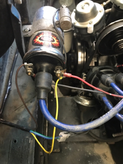
Joel, now I’m confused again. While I’m having no issues at all and the car is running great I was worried that I might have a premature failure since Petronix said to use 3 ohm coil for a six cylinder. Here is a pic of my wiring. Do I have it right?
Gary Roberson
66 Vert 140 4-sp Corsa “clone”
66 Vert 140 4-sp Corsa “clone”
-
joelsplace
- Posts: 2599
- Joined: Wed Oct 13, 2010 12:51 pm
- Location: Northlake, TX
Re: Flame Thrower ignition coil
Check the voltage at the coil + with the engine running. If it is significantly less than 12v then run the 1.5 ohm coil. If it shows close to the same voltage you get at the battery then run the 3 ohm coil.
160 Corvairs, 5 Ultravans and counting
Northlake, TX
Northlake, TX
Re: Flame Thrower ignition coil
Thanks Joel, why didn’t I think of that  But now I think I see what Brad has been trying to tell me. If I have the red wire from the Igniter attached to the + side of the coil, the Igniter is being fed the reduced voltage with the engine running, correct?
Gary Roberson
66 Vert 140 4-sp Corsa “clone”
66 Vert 140 4-sp Corsa “clone”
-
joelsplace
- Posts: 2599
- Joined: Wed Oct 13, 2010 12:51 pm
- Location: Northlake, TX
Re: Flame Thrower ignition coil
Yes as long as the resistor wire is intact.
160 Corvairs, 5 Ultravans and counting
Northlake, TX
Northlake, TX
- bbodie52
- Corvair of the Month

- Posts: 12137
- Joined: Mon Aug 06, 2012 12:33 pm
- Location: Lake Chatuge Hayesville, NC
- Contact:
Re: Flame Thrower ignition coil
Since you are using a Pertronix breakerless (magnetic pulse) ignition system, and you also purchased a 3 ohm ignition coil, you need a full-time 12 Volt feed to the ignition system, with no resistance wire or other resistor in the circuit so that you can provide proper battery voltage (switched by the ignition switch in the dashboard) to power the electronic circuitry inside the Pertronix module. The 3 ohm coil you purchased is rated for use without an external ballast resistor. You can tap off of the wiring harness on the firewall side of the engine compartment multi-connector. This will provide a full 12 VDC switched power source from the ignition switch, before it is reduced by the factory inline resistor wire. The portion of the harness that includes the resistor wire and the connection to the starter solenoid is no longer needed, and can be bypassed.
The schematic below is from an early Corvair, but it is representative of what you need to accomplish on you late model Corvair, in bypassing the resistor wire portion of the original circuit.
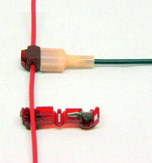
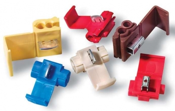
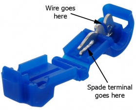
This type of connector may simplify the taps into the Corvair wiring harness...
The Problem with Wire-Tap Connectors
 http://tech.bareasschoppers.com/resourc ... onnectors/
The illustration below shows the point were you can tap in to the existing engine compartment wiring harness to bypass the existing ballast resistor circuits and provide a direct tie to the ignition switch 12 VDC power source for an aftermarket electronic ignition system that requires 12 VDC full-time. 1962-1963, 1964, and 1965 Corvair harnesses are shown...
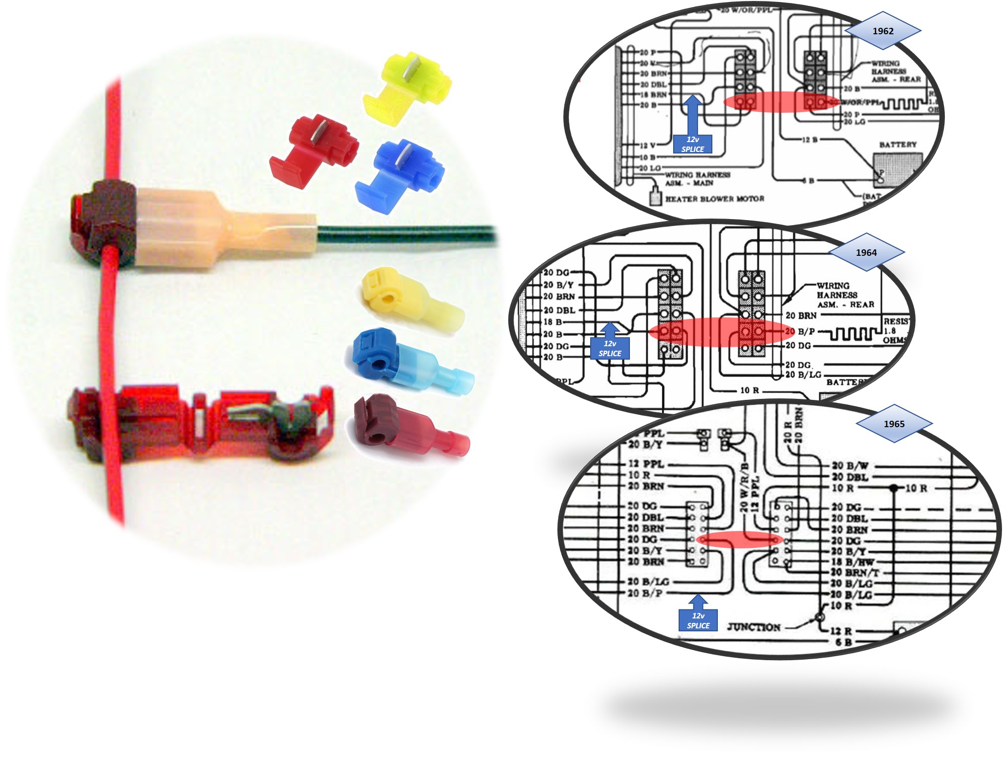
I have never personally had any problem with those wire tap connectors. But because of the possibility of an intermittent electrical connection, I would not choose them for critical operational circuits like the ignition system power for an add-on system like an electronic ignition system. A loose or intermittent connection on a tail light or brake light circuit affecting add-on temporary lights could be easily corrected, if they occurred. But I have found those tee-taps to be reliable and easy to install.
It is not a bad idea to relocate the coil mount position. The standard installation of the ignition coil was always mounting it directly on the right cylinder head. The cylinder head on an air cooled engine gets very hot, and a significant portion of that heat can be transferred via the coil mounting bracket to the coil body itself. I would recommend relocating any coil as shown in the pictures below.
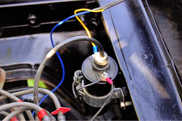
The schematic below is from an early Corvair, but it is representative of what you need to accomplish on you late model Corvair, in bypassing the resistor wire portion of the original circuit.
This type of connector may simplify the taps into the Corvair wiring harness...
The Problem with Wire-Tap Connectors


The illustration below shows the point were you can tap in to the existing engine compartment wiring harness to bypass the existing ballast resistor circuits and provide a direct tie to the ignition switch 12 VDC power source for an aftermarket electronic ignition system that requires 12 VDC full-time. 1962-1963, 1964, and 1965 Corvair harnesses are shown...
I have never personally had any problem with those wire tap connectors. But because of the possibility of an intermittent electrical connection, I would not choose them for critical operational circuits like the ignition system power for an add-on system like an electronic ignition system. A loose or intermittent connection on a tail light or brake light circuit affecting add-on temporary lights could be easily corrected, if they occurred. But I have found those tee-taps to be reliable and easy to install.
It is not a bad idea to relocate the coil mount position. The standard installation of the ignition coil was always mounting it directly on the right cylinder head. The cylinder head on an air cooled engine gets very hot, and a significant portion of that heat can be transferred via the coil mounting bracket to the coil body itself. I would recommend relocating any coil as shown in the pictures below.

Brad Bodie
Lake Chatuge, North Carolina
 1966 Corvair Corsa Convertible
Lake Chatuge, North Carolina
 1966 Corvair Corsa Convertible
Re: Flame Thrower ignition coil
Thanks for that 12v feed info Brad. However, Brad, Joel, I checked voltage at the + side of the coil with the engine running and got 12-13v! That’s baffling as that indicates that the resistor circuit had been bypassed, yet I see no indication whatsoever of ANY wiring modifications.I also checked the voltage at the battery with the engine running and it showed 15.5-16.1v. That seems high??
Gary Roberson
66 Vert 140 4-sp Corsa “clone”
66 Vert 140 4-sp Corsa “clone”
-
joelsplace
- Posts: 2599
- Joined: Wed Oct 13, 2010 12:51 pm
- Location: Northlake, TX
Re: Flame Thrower ignition coil
You may have a bad meter or a bad voltage regulator. Your resistor wire is still there if you have 4V difference between the coil and battery. Try the meter between the coil positive and battery positive. You should get less than 1V if there is no resistor. If you get 3 or more then you have the resistor.
Check the meter on another vehicle to see if you are still getting 16V to verify the meter.
Check the meter on another vehicle to see if you are still getting 16V to verify the meter.
160 Corvairs, 5 Ultravans and counting
Northlake, TX
Northlake, TX
- bbodie52
- Corvair of the Month

- Posts: 12137
- Joined: Mon Aug 06, 2012 12:33 pm
- Location: Lake Chatuge Hayesville, NC
- Contact:
Re: Flame Thrower ignition coil
1. Engine OFF
2. Ground Coil Negative Terminal!
3. Ignition Key ON.
4. Measure voltage at coil positive terminal now, with current flowing through the circuit from the ignition switch to the ground connection.
5 Turn key OFF
6. Remove temporary ground wire from coil negative terminal.
If current is not flowing through the circuit to ground, you have an OPEN circuit and it will always read battery voltage (12.5 VDC). If the ballast resistor wire is actually present, its impact on the circuit can only be measured with current flowing through the circuit to ground. You will probably measure about 7 VDC in this test.
Brad Bodie
Lake Chatuge, North Carolina
 1966 Corvair Corsa Convertible
Lake Chatuge, North Carolina
 1966 Corvair Corsa Convertible