I have linked all three pages from the 1962 shop manual supplement that show the Corvair 95 wiring schematic. Left clicking on this image will enlarge the schematic on the screen so that you can view it in detail and scroll around to trace a circuit.
I have also attached a copy of the appropriate supplement section that contains the individual schematics.
Power for the bright filaments in the 1034/1157 bulbs in the rear tail light housings comes from two sources that route to the TURN SIGNAL SWITCH: 20Y (Intermittent 12V DC from the Flasher Module in the Fuse Block) or 20N (12V DC from the STOP LAMP SWITCH at the brake pedal). The turn signal switch (in the neutral position) passes the voltage from the STOP LAMP SWITCH straight through to the 20V wire (Right-Hand Tail Lamp) and the 20P wire (Left-Hand Tail Lamp). When the driver steps on the brake pedal, the circuit is completed and both brake lights are illuminated.
When the driver moves the turn signal switch to either the right or left turn signal, the power source from the selected side is temporarily disconnected from the STOP LAMP SWITCH and is reconnected to the Flasher in the Fuse Block. The front 1034/1157 filament is simultaneously connected to the same flasher power source, and both the front and rear turn signal lamps flash intermittently until the turn is cancelled.
(The rear 1034/1157 bulb filament on the opposite side remains connected to the STOP LAMP SWITCH, so that the rear stop lamp will illuminate continuously whenever the driver steps on the brake pedal. In this way one side can indicate a turn, while the other side can still indicate the application of the brakes).
 Viewed 1649 times")
- 1962 Corvair 95 Full Schematic (Left-Click to Enlarge)
Do the rear brake lights work when the tail (running) lights are on? If they do then the tail lamp socket ground is likely OK. The wiring harness from the turn signal switch to the rear sockets is the same for both the rear turn signals and brake lamps (on each side, respectively). So if both brake lamps illuminate when you step on the brake pedal, this confirms a good circuit from the turn signal switch to each rear lamp socket, through each bulb filament, and on to the socket ground.
If the turn signal flashes on one side, but not the other, this confirms a good power circuit from the fuse block and flasher to the turn signal switch.
Two things might disrupt the turn signal light on the right side:
(1) A faulty circuit or bulb on the same side, in the front. The flasher will only cycle on and off if it is properly loaded by
TWO BULBS (front and rear) and the instrument panel turn signal lamp. If the front circuit or bulb on that side is bad, the current draw will be too low for the flasher to cycle properly, and it might be "stuck". You can confirm the condition of the rear bulbs and bulb circuits by simply stepping on the brake pedal. But the front bulb condition and bulb circuit must also be confirmed. A corroded socket, faulty bulb filament, bad circuit, or bad socket ground in the front could prevent the flasher from operating properly due to inadequate current draw on that side.
(2) A faulty internal contact inside the turn signal switch could prevent flasher power from reaching the front and rear turn signal lamps when the turn signal switch is engaged on the side that is not working.
If testing confirms that the front and rear bulb circuits are functioning properly between the turn signal switch and the bulb sockets, a bad turn signal switch may be the cause of the turn signal failure. (The function of the turn signal switch can be tested with a test light or ohm meter with the turn signal switch unplugged from the wiring harness. You will have to figure out which connectors on the socket are related to the flasher power and the front/rear bulbs used for turn signals (using the wire color code will point you to the correct connectors) With a continuity tester, you should be able to test for continuity between the flasher connector and the left or right bulb wire terminals. Moving the turn signal lever to the left or right should establish an electrical connection between the flasher connector and the bulb connectors on the selected side).
RIGHT SIDE TURN SIGNAL [20Y (Flasher) >> 20DBL (Right Front) and 20V (Right Rear)]
LEFT SIDE TURN SIGNAL [20Y (Flasher) >> 20LBL (Left Front) and 20P (Left Rear)]
 http://www.corvair.com/user-cgi/catalog ... IN&page=87
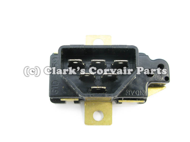
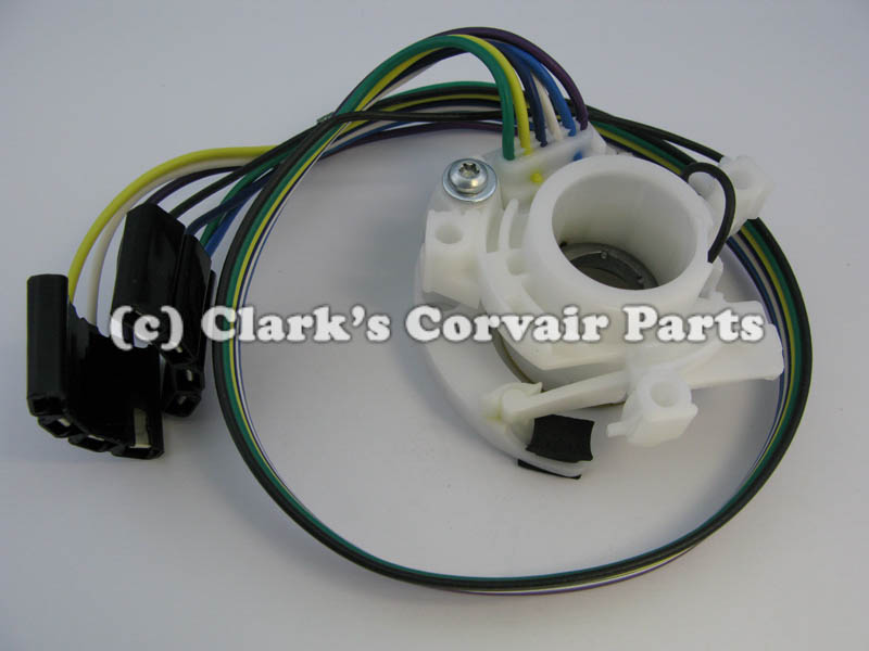
 Part number C861A: 61-63 VAN DIRECTIONAL SWITCH CABLE CASING = C8078 , WIRE = C8076
Weight: 0 lbs 6 oz
Catalog Pages(s): 87
Price: $ 35.75