Flame Thrower ignition coil
Re: Flame Thrower ignition coil
Thanks Brad, I’ll do that and let you know what I find!
Gary Roberson
66 Vert 140 4-sp Corsa “clone”
66 Vert 140 4-sp Corsa “clone”
- bbodie52
- Corvair of the Month

- Posts: 12137
- Joined: Mon Aug 06, 2012 12:33 pm
- Location: Lake Chatuge Hayesville, NC
- Contact:
Re: Flame Thrower ignition coil
As I mentioned earlier, this is the method Pertronix recommends on their website (see below)...

Brad Bodie
Lake Chatuge, North Carolina
 1966 Corvair Corsa Convertible
Lake Chatuge, North Carolina
 1966 Corvair Corsa Convertible
Re: Flame Thrower ignition coil
Brad, I verified the accuracy of my multimeter. Our Prius checked 12.92v engine off and 14.22v at the battery with the engine running. Per your test with the negative side of the coil grounded, I got 4.69v., checked at the positive side of the coil ignition on, engine not running. With the engine running and temporary ground removed, I got 17.1v at the battery and 14.5v at the coil with the engine running at 1500rpm!!! It appears that the resistor circuit is in place and doing its job, correct? Now the issue of the high voltage output. I see in the Corvair service manual, that the external voltage regulator is adjustable to produce the correct alternator output. However, the service calls for a 25ohm resistor to be installed in the circuit in order to test and adjust. I don’t see why I can’t just adjust the voltage down per the multimeter without adding the fancy 25ohm circuit???
Gary Roberson
66 Vert 140 4-sp Corsa “clone”
66 Vert 140 4-sp Corsa “clone”
- bbodie52
- Corvair of the Month

- Posts: 12137
- Joined: Mon Aug 06, 2012 12:33 pm
- Location: Lake Chatuge Hayesville, NC
- Contact:
Re: Flame Thrower ignition coil
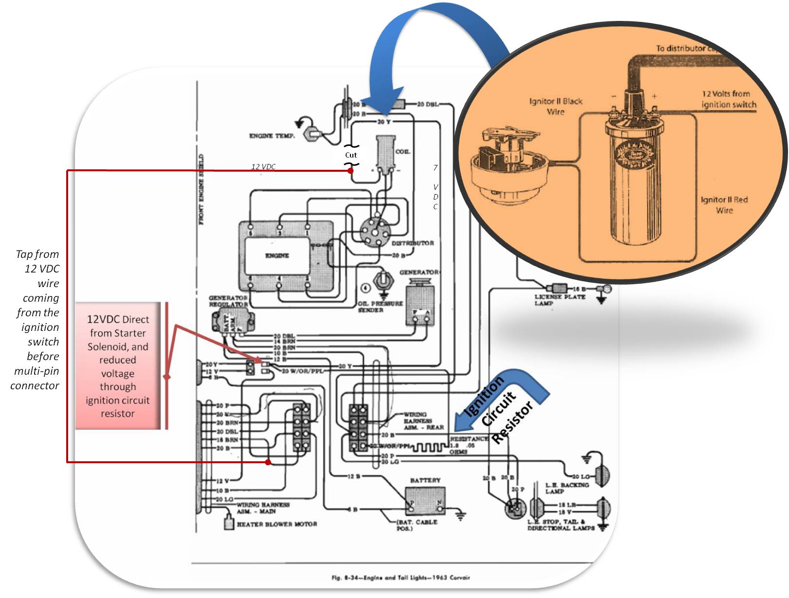
4.69 VDC is too low. About 7 VDC is expected with a stock coil in-place. Do you have the 3.0 ohm coil installed? If you do, this coil, plus an external ballast resistor wire, would provide a total circuit resistance of approximately 4.8 ohms (3.0 (coil) + 1.8 (resistor wire)). The factory 1.8 ohm ballast resistor wire is intended to be used with a factory Delco coil rated at 1.28 - 1.42 ohms — providing a total of approximately 3 ohms. When you installed your 3 ohm coil, you made it necessary to remove or bypass the external ballast resistor wire in the Corvair wiring harness. As I stated earlier, with a Pertronix Ignitor and an aftermarket 3.0 ohm coil in your Corvair, the factory ballast resistor wire needs to be bypassed (FIGURE 2 below) to prvide the correct voltage to power the Pertronix Ignitor and to power the 3.0 ohm coil and obtain the desired spark plug firing voltage.

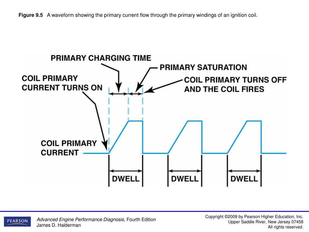
Reading the voltage at the coil with the engine running would be two voltage levels switching back and forth between voltage with the coil negative terminal grounded and with it open (switching back and forth as the Pertronix transistor connects the coil negative terminal to GROUND to charge the coil (with current flowing through the primary coil winding) and collapsing the magnetic field to discharge the coil and fire a spark plug. The multimeter cannot actually display these two voltage extremes because they are switching back and forth too fast — six times for each distributor revolution, so you get something in-between battery charging voltage and voltage reduced by the ballast resistor each time the coil negative is grounded. An oscilloscope can display this pattern and the two voltage levels as the negative terminal switches between ground and open, but a multimeter display (digital or analog) cannot really provide a meaningful voltage reading at the coil with the engine running.

A charging voltage of 17.1 VDC is too high. With the engine off and everything in the car turned off, your battery voltage should be about 12.5 VDC. With the engine running and the alternator providing a charging voltage to the battery, the voltage is usually about 14.5 VDC. If your alternator output is at 17.1 VDC or higher, the voltage regulator may be faulty. The 1965 Corvair Chassis Shop Manual - SECTION 6Y - ENGINE ELECTRICAL (attached) states that the charging voltage output should be between 13.5 VDC and 15.2 VDC. If you have an external voltage regulator and it is the original adjustable design, you may be able to adjust the charging voltage to meet these standards. If you have an alternator with an external or internal solid state regulator, it may not be adjustable and you may have to consider replacing the external regulator or the alternator to correct a high voltage charging voltage condition. (On my Corvair Monza the battery voltage reads 12.5 VDC, and with the engine running the charging voltage typically reads 14.5 - 15 VDC).


Reading the voltage at the coil with the engine running would be two voltage levels switching back and forth between voltage with the coil negative terminal grounded and with it open (switching back and forth as the Pertronix transistor connects the coil negative terminal to GROUND to charge the coil (with current flowing through the primary coil winding) and collapsing the magnetic field to discharge the coil and fire a spark plug. The multimeter cannot actually display these two voltage extremes because they are switching back and forth too fast — six times for each distributor revolution, so you get something in-between battery charging voltage and voltage reduced by the ballast resistor each time the coil negative is grounded. An oscilloscope can display this pattern and the two voltage levels as the negative terminal switches between ground and open, but a multimeter display (digital or analog) cannot really provide a meaningful voltage reading at the coil with the engine running.

A charging voltage of 17.1 VDC is too high. With the engine off and everything in the car turned off, your battery voltage should be about 12.5 VDC. With the engine running and the alternator providing a charging voltage to the battery, the voltage is usually about 14.5 VDC. If your alternator output is at 17.1 VDC or higher, the voltage regulator may be faulty. The 1965 Corvair Chassis Shop Manual - SECTION 6Y - ENGINE ELECTRICAL (attached) states that the charging voltage output should be between 13.5 VDC and 15.2 VDC. If you have an external voltage regulator and it is the original adjustable design, you may be able to adjust the charging voltage to meet these standards. If you have an alternator with an external or internal solid state regulator, it may not be adjustable and you may have to consider replacing the external regulator or the alternator to correct a high voltage charging voltage condition. (On my Corvair Monza the battery voltage reads 12.5 VDC, and with the engine running the charging voltage typically reads 14.5 - 15 VDC).
- Attachments
-
- 1965 Corvair Chassis Shop Manual - SECTION 6Y - ENGINE ELECTRICAL.pdf
- 1965 Corvair Chassis Shop Manual - SECTION 6Y - ENGINE ELECTRICAL
- (8.51 MiB) Downloaded 61 times
-
- 1965 Corvair Chassis Shop Manual - SECTION - SPECIFICATIONS.pdf
- 1965 Corvair Chassis Shop Manual - SECTION - SPECIFICATIONS
- (2.83 MiB) Downloaded 51 times
Brad Bodie
Lake Chatuge, North Carolina
 1966 Corvair Corsa Convertible
Lake Chatuge, North Carolina
 1966 Corvair Corsa Convertible
Re: Flame Thrower ignition coil
Brad, the 4.69v is with the 1.8ohm coil installed. If that is too low, what would you suggest is wrong? I have a brand new 3.0ohm coil, but have never installed it. I do have the stock charging system with the external voltage regulator.
Gary Roberson
66 Vert 140 4-sp Corsa “clone”
66 Vert 140 4-sp Corsa “clone”
- bbodie52
- Corvair of the Month

- Posts: 12137
- Joined: Mon Aug 06, 2012 12:33 pm
- Location: Lake Chatuge Hayesville, NC
- Contact:
Re: Flame Thrower ignition coil
The easiest thing to do is to install your 3.0 ohm coil and run a bypass wire from the multiconnector wire on the firewall side (power from the ignition switch) directly to the coil positive terminal, and then power the Pertronix module from the same coil positive terminal, as shown in Figure 2. Then the resistor wire in the harness is out of the circuit and life goes on, so you can focus on adjusting or replacing your voltage regulator and getting your charging voltage within specs.
When its all over you will receive your Corvair electrical merit badge!


When its all over you will receive your Corvair electrical merit badge!
Brad Bodie
Lake Chatuge, North Carolina
 1966 Corvair Corsa Convertible
Lake Chatuge, North Carolina
 1966 Corvair Corsa Convertible
Re: Flame Thrower ignition coil
Brad, OK, that sounds like a good plan. When I install the 12v feed to bypass, I need to disconnect the current feed to the coil, right? Can’t wait to get my electrical merit badge
Gary Roberson
66 Vert 140 4-sp Corsa “clone”
66 Vert 140 4-sp Corsa “clone”
- bbodie52
- Corvair of the Month

- Posts: 12137
- Joined: Mon Aug 06, 2012 12:33 pm
- Location: Lake Chatuge Hayesville, NC
- Contact:
Re: Flame Thrower ignition coil
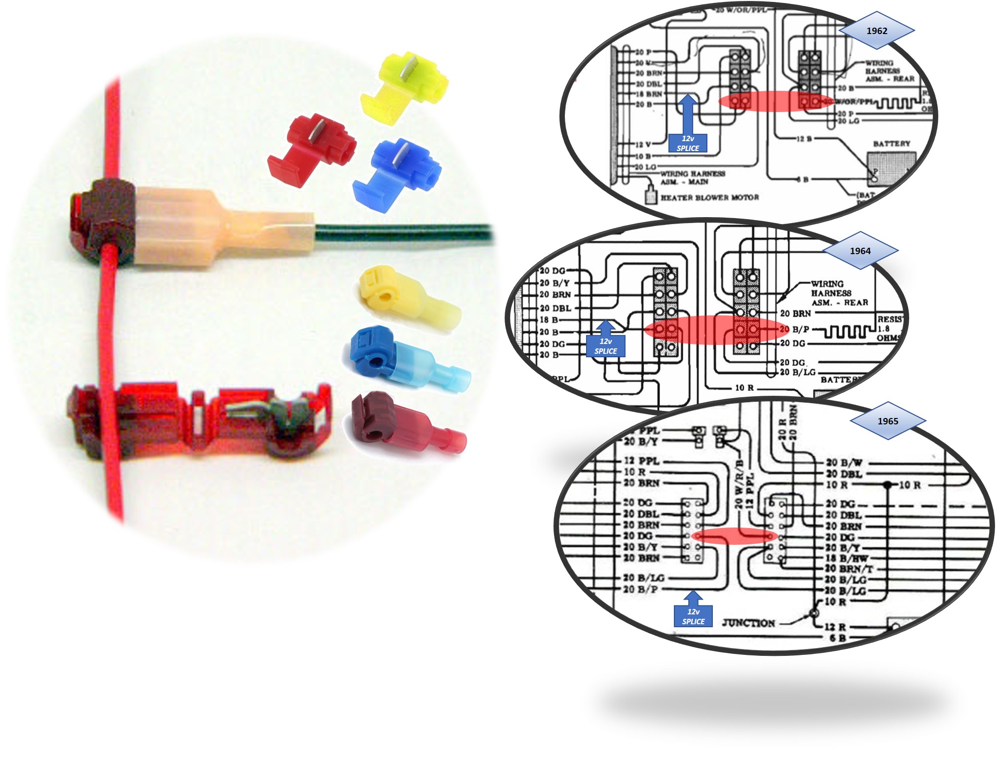
When you locate the correct wire that leads into the 12 pin multiconnector (firewall side of the connector) and tap into it, you are picking up the 12 VDC output (switched) from the ignition switch in the dashboard. Voltage will only be present there when the key is in the ON position. The wire is a 12 Gauge wire (labeled 12 P, 12 Gauge Pink), so the wire spliced into the harness at that point should be routed and secured around the perimeter harness in the engine compartment and attached to the new 3.0 ohm ignition coil (positive terminal) in place of the old Yellow wire, labeled 20 Y, that was attached to the old 1.5 ohm coil. The red Pertronix Ignitor power wire that goes to the distributor ignition module also connects to the new ignition coil positive terminal, to extend that same ignition switch power source to the Pertronix Ignitor breakerless ignition module. (See Fig. 2 in the bottom diagram). The old 20 Y wire is still remains connected to the starter solenoid and ignition switch, so the end of the wire needs to be sealed or taped with electrical tape (or removed) to ensure that it will not come into contact with any chassis ground and short out the circuit. The end result will be that the Pertronix Ignitor module and the new 3 ohm coil will always have full 12 VDC battery voltage to power them from the ignition switch when the switch is in the ON position.
1966-1969 had only 2 color changes, The Black/Pink Stripe for the Ignition hot wire found in the dashboard wiring went to solid Pink, and the Black/Yellow Stripe for the Ignition coil from the starter solenoid harness plug went to solid Yellow.


1966-1969 had only 2 color changes, The Black/Pink Stripe for the Ignition hot wire found in the dashboard wiring went to solid Pink, and the Black/Yellow Stripe for the Ignition coil from the starter solenoid harness plug went to solid Yellow.
Brad Bodie
Lake Chatuge, North Carolina
 1966 Corvair Corsa Convertible
Lake Chatuge, North Carolina
 1966 Corvair Corsa Convertible
Re: Flame Thrower ignition coil
Thanks Brad, I fully understand your introductions and schematics. I’ll let you know when I get it done and you can then send me my merit badge
Gary Roberson
66 Vert 140 4-sp Corsa “clone”
66 Vert 140 4-sp Corsa “clone”
Re: Flame Thrower ignition coil
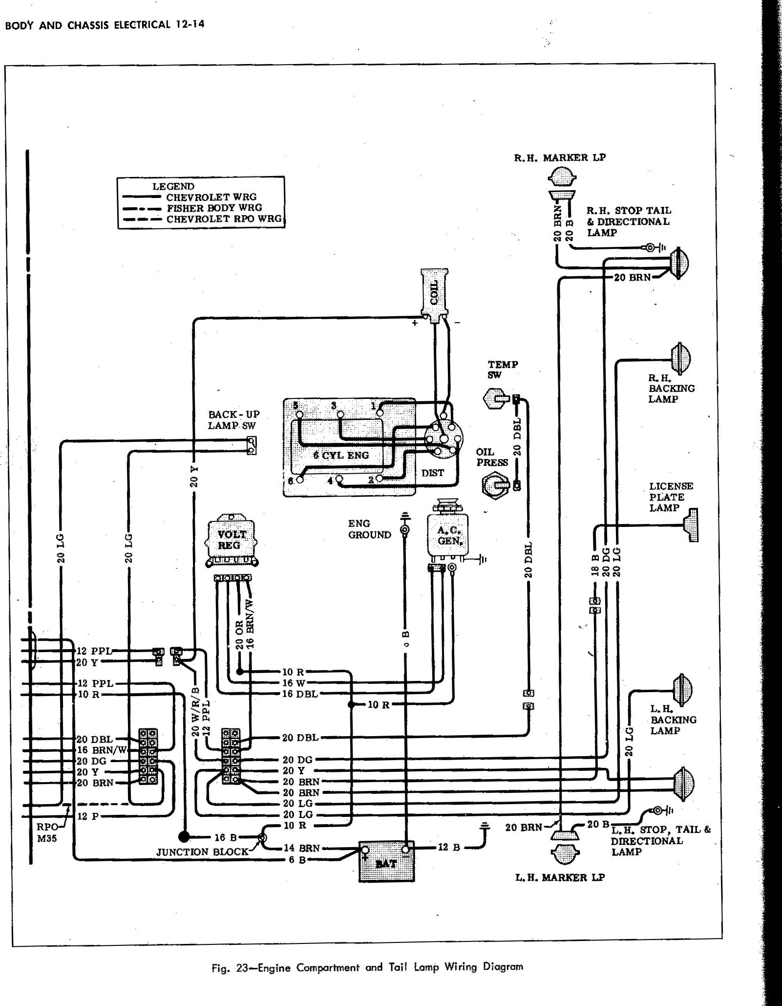
Brad, I finally got around to installing the 3ohm coil and the jumper wire to feed 12v to the coil and the Petronix ignition. I don’t know if it’s my imagination or not, but it sure seems to run smoother and pull harder at higher RPM! The wire I tapped into for the switched 12v feed was the one In the 66 service manual schematic that is two terminals down from the red 10ga from the alternator. Right next to the terminal with the two 20 B/LG wires leading to it. Funny thing, however, that wire, according to the schematic, runs to the two terminal connector the goes to the starter. On my car, that wire heads somewhere to the back of the car and appears to be solid brown???
Gary Roberson
66 Vert 140 4-sp Corsa “clone”
66 Vert 140 4-sp Corsa “clone”
- bbodie52
- Corvair of the Month

- Posts: 12137
- Joined: Mon Aug 06, 2012 12:33 pm
- Location: Lake Chatuge Hayesville, NC
- Contact:
Re: Flame Thrower ignition coil
It depends on which way you are looking. The wire that leaves the connector, in the direction of the starter solenoid connector, is the resistor wire. It is spliced at the starter solenoid connector and continues on to the ignition coil. With that resistor wire in the circuit, it is providing the coil with about 7 VDC. When the starter is engaged, the solenoid feeds the same coil wire a full 12 VDC battery voltage to boost the coil output during engine cranking. This helps the slowly turning cold engine to start. When the engine starts, the driver releases the key and the starter solenoid disengages, leaving the coil circuit with only 7 VDC (a voltage reduced by the resistor wire). That reduced voltage was needed to help the stock Delco coil to run cooler, and to prolong the operating life of the ignition points by reducing arcing and burning of the contacts as the switch opens and closes. 7 VDC was considered to be the minimum adequate voltage to keep a warm engine running, while helping the points to last longer between tune-ups. The lower voltage also helped the stock coil to run at cooler internal temperatures, which extended its operational lifespan....Funny thing, however, that wire, according to the schematic, runs to the two terminal connector the goes to the starter...
Your wiring modification taps into the ignition switch wire JUST BEFORE it reaches the resistor wire. At that point it is at full battery voltage (12 VDC) and has not yet reached the resistor wire. Your newly installed jumper bypass wire goes straight to the new 3 ohm coil positive terminal, and completely bypasses the resistor wire and the starter solenoid connector. In this way that resistor wire portion of the old wiring is no longer actively feeding the coil. The coil (and associated Pertronix Ignitor electronic module inside the distributor) is now powered directly from the ignition switch in the dashboard, without interference from the resistor wire. This modified circuit now provides the 3.0 ohm coil and the Pertronix Ignitor module with the full 12 VDC power they were designed for. (The original resistor wire circuit was designed to support a stock factory Delco 1.5 ohm coil connected to ignition points. Since that 1.5 ohm stock coil and the points are no longer present in the car, the factory resistor wire is no longer needed either. Your wiring modification has taken care of that and matched your Corvair wiring to the new requirements of your upgraded modern ignition system).
Brad Bodie
Lake Chatuge, North Carolina
 1966 Corvair Corsa Convertible
Lake Chatuge, North Carolina
 1966 Corvair Corsa Convertible