I was having trouble getting my "63" to start, It would only catch when the battery was charged to the max. then it would run fine. I felt it just wasn't getting enough pop, changed plugs, coil and reset electronic ignition. Then I noticed the yellow / black? wire had come off the starter post. Hooked that back up and it popped first crank, but would die as soon as I let the key off the start position. I noted that with the key on I have no juice to the coil. Replaced ignition switch to no avail. HELP
Dave
wiring problem
Re: wiring problem
When you key the starter, the secondary post on the starter solenoid ( second small stud) puts 12Volts to the coil to start. Once you let go of the starter, your normal ignition battery source feeds the coil. The fact that your engine shuts off after you let go of the starter means your primary ignition source is bad. Where ? Between the ignition switch and the coil. You can verify this by just running a jumper between your 12 V battery post and the positive side of the coil. Key the starter, it should start and stay running. Remove the jumper and it should shut off the engine.
Ballast resistor wire is burned up in my opinion. Advice is free and worth every cent
Ballast resistor wire is burned up in my opinion. Advice is free and worth every cent
Prior Corvair owner 30+ years ago
Just acquired 64 Spyder, 66 & 65 Corsa,
adding to 69 Corvette BB, 67 GTO,
2015 Corvette Z06,
04 996TT Porsche,
04 Caterham Super 7
just sold 87 Porsche 930 Turbo (Thank God)
Just acquired 64 Spyder, 66 & 65 Corsa,
adding to 69 Corvette BB, 67 GTO,
2015 Corvette Z06,
04 996TT Porsche,
04 Caterham Super 7
just sold 87 Porsche 930 Turbo (Thank God)
-
bbodie52

- Corvair of the Month

- Posts: 12140
- Joined: Mon Aug 06, 2012 12:33 pm
- Location: Lake Chatuge Hayesville, NC
- Contact:
Re: wiring problem
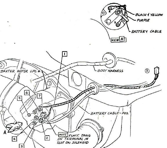
The ignition coil positive terminal on the Corvair receives power from two sources. The first source is the ignition switch when it is in the ON position. Turning the key ON provides switched power to a number of circuits in the car. If you locate the ignition switch in the bottom diagram below (near the top-center portion of the schematic diagram) you will see that it has three terminals, labeled "C", "S" and "R".
"R" - Receives 12 VDC from the battery power source at all times. You will see the wire connected to a wiring junction that powers the horn relay, the main light switch, the dome lamp circuit, the cigarette lighter, and the ignition switch.
"S" - Sends power to the starter solenoid to engage the starter whenever the key is turned to START.
"C" - Sends switched power to another wire junction that is only powered when the key is in the ON position. This powers things like the PRES/TEMP and GEN/FAN warning lights, the Gas Gauge, and the ignition coil.
If the key is ON, and you see the instrument panel warning lights illuminated, then you know that power is being fed from the ignition switch to the junction that powers both the warning lights AND the coil. If the instrument panel warning lights are on, but you can measure no voltage between the coil positive terminal and Ground, you should first suspect the 8-pin multi-connector in the engine compartment. With the key ON, power enters the 8-pin multi-connector via the 18 BRN (18 gauge Brown) wire. On the other side of the connector, the voltage is fed through a special ballast resistor wire labeled 20 W/OR/PPL that reduces the voltage from 12 VDC to approximately 7 VDC. After passing through the resistor wire, the voltage passes across a 2 pin multi-connector coming from the starter solenoid (labeled 20 Y - 20 gauge yellow). The 20Y wire then continues on to the ignition coil positive terminal.
The 8-pin multi-connector is often a source of trouble. As it ages, gets wet and dirty, is subjected to vibration and heat, etc. the eight metal pins inside the plastic housing can be come bent, loose, or corroded. You should separate the two halves and check for voltage at the 18 BRN wire when the key is on. If the metal pins are not making good contact, the voltage coming from the firewall side and instrument panel may not be getting through to the other side. You can inspect and clean the two sides of the connector to try to restore the power connection if this connector is determined to be the trouble area. If power is getting through the connector, continue to check for electrical continuity through the resistor wire, and on to the coil to determine where the power is being interrupted.
The other source of power to the coil is from the starter solenoid "R" terminal. When the ignition key is turned to START, power is applied to the thick 12V (12 gauge Violet) wire that is connected to the "S" terminal on the solenoid. This energizes the solenoid, to engage the starter gear and to apply battery power to the starter motor. At the same time, a full 12 VDC is applied from the solenoid via the "R" terminal and yellow wire to the coil. The higher 12 VDC temporarily overrides the lower 7 VDC fed to the coil via the resistor wire. This higher voltage increases the spark voltage coming from the coil to the spark plugs, which enhances engine starting. As soon as the engine starts and the operator releases the ignition key, the higher voltage is switched off, leaving only the lower 7 VDC coming through the resistor wire. Using lower voltage during normal engine operation lowers the current through the ignition points, which reduces arcing and burning of the points and prolongs their operational life. Consequently the spark voltage output of the coil is also reduced, but it is still considered adequate for normal engine operation once it has started.
If you only hear the engine fire while the key is held to START, but the engine dies when you release the key and the starter solenoid disengages, the operating voltage from the ignition switch is probably not making it from the switch to the coil. If the warning lights come on with the key ON, but the coil receives no power, the multi-connector or the resistor wire may be suspect.
NOTE: The illustration showing the starter and harness is from a 1965 diagram so the wire color codes are slightly different than the actual 1963 configuration.
Brad Bodie
Lake Chatuge, North Carolina
 1966 Corvair Corsa Convertible
Lake Chatuge, North Carolina
1966 Corvair Corsa Convertible
Re: wiring problem
Does your electronic ignition need a full 12 volts to properly operate?
Jeremy (cad-kid)
Kronenwetter, WI (Central Wisconsin)
SOLD 9-2016 65 Monza 4spd/140
My 65 Monza thread
 My YouTube page
Kronenwetter, WI (Central Wisconsin)
SOLD 9-2016 65 Monza 4spd/140
My 65 Monza thread
Re: wiring problem
I think Brad narrowed it down to the 8 pin connector in the engine connector. In any case, that's an easy place to check voltage. If the power reaches the connector, the receiving end of the connector may not be making the connection, or the 1.8 ohm ballast resistor wire burned up, but from there it's easy to check and figure out.
My 69 Vette had a similar problem but it was intermittent. I'd shut the car off in the driveway but when I'd go to restart it, nothing. Dead as if someone stole the battery. I even checked to see if I still had the battery. Some of the male spade connectors had lightly pulled out of the plastic housing. Cold, it would make contact but once it would heat up, the contacts expanded and would pull away leaving the engine dead as a doornail. I hunted a while to find the cause of my troubles but when a friend told me of his similar problem with his 66 Vette, I then knew where the problem was. In the case of the Vette, having a car lift was necessary to get to the connector on the firewall just below the brake booster. It had heated up enough to almost melt the plastic housing. General Motors in the 60's and 70's, quality was not their strong suit.
My 69 Vette had a similar problem but it was intermittent. I'd shut the car off in the driveway but when I'd go to restart it, nothing. Dead as if someone stole the battery. I even checked to see if I still had the battery. Some of the male spade connectors had lightly pulled out of the plastic housing. Cold, it would make contact but once it would heat up, the contacts expanded and would pull away leaving the engine dead as a doornail. I hunted a while to find the cause of my troubles but when a friend told me of his similar problem with his 66 Vette, I then knew where the problem was. In the case of the Vette, having a car lift was necessary to get to the connector on the firewall just below the brake booster. It had heated up enough to almost melt the plastic housing. General Motors in the 60's and 70's, quality was not their strong suit.
Prior Corvair owner 30+ years ago
Just acquired 64 Spyder, 66 & 65 Corsa,
adding to 69 Corvette BB, 67 GTO,
2015 Corvette Z06,
04 996TT Porsche,
04 Caterham Super 7
just sold 87 Porsche 930 Turbo (Thank God)
Just acquired 64 Spyder, 66 & 65 Corsa,
adding to 69 Corvette BB, 67 GTO,
2015 Corvette Z06,
04 996TT Porsche,
04 Caterham Super 7
just sold 87 Porsche 930 Turbo (Thank God)
-
flat6_musik
- Posts: 2659
- Joined: Sun Apr 04, 2010 10:03 am
- Location: Hesperia, CA
Re: wiring problem
You definitely want to explore this too.........cad-kid wrote:Does your electronic ignition need a full 12 volts to properly operate?
-
bbodie52
- Corvair of the Month
- Posts: 12140
- Joined: Mon Aug 06, 2012 12:33 pm
- Location: Lake Chatuge Hayesville, NC
- Contact:
Re: wiring problem

I'm a little confused about the ignition configuration on this Corvair...
Apparently an electronic ignition was added in 2014. I'm not sure what "reset electronic ignition" means. If the electronic ignition system is a Pertronix, it would be happier with a full 12 VDC power source and no ballast resistor. If it is a Crane Cams XR700 system it needs a reduced voltage via a ballast resistor to prevent overheating of the electronics module. However, the Crane Cams XR3000 system needs a full 12 VDC.Dave wrote:...checked vacuum changed coil,checked fuel filters, set timing and points. am at a loss
Dave [Mar 26, 2013]
...Timing is good and have electronic ignition. [Mar 20, 2014]
...I felt it just wasn't getting enough pop, changed plugs, coil and reset electronic ignition... [Feb 13, 2015]
- Attachments
-
- Crane Cams XR700 Optically Triggered Installation Instructions.pdf
- Crane Cams XR700 Optically Triggered Installation Instructions
- (3.38 MiB) Downloaded 26 times
-
- Pertronix Ignitor 12v neg Instructions.pdf
- Pertronix Ignitor 12v neg Instructions
- (73.1 KiB) Downloaded 33 times
-
- Pertronix 91162A Ignitor II Instructions.pdf
- Pertronix 91162A Ignitor II Instructions
- (1.01 MiB) Downloaded 30 times
Brad Bodie
Lake Chatuge, North Carolina
1966 Corvair Corsa Convertible
Lake Chatuge, North Carolina
1966 Corvair Corsa ConvertibleRe: wiring problem
Thank you all as it turns out the dummy who replaced the starter (that would be me) put the yellow wire to the coil on the R post with the purple wire instead of the S post 
-
BIGTWIN
- Corvair of the Month
- Posts: 312
- Joined: Fri Jan 18, 2013 3:05 pm
- Location: Mont Belvieu, Texas
- Contact:
Re: wiring problem
Man, I HATE it when stuff like that happens. I do it on occasion too so don't feel like the Lone Ranger. Usual top quality assistance guys. 
1961 Monza
"Outside of a dog, a book is man's best friend.
Inside a dog it's too dark to read."
"Outside of a dog, a book is man's best friend.
Inside a dog it's too dark to read."