Hello all
Hello all
I bought a 1963 rampside that hasn't run in years and I'm working towards making it driveable. I went through the fuel system and it's getting fuel, but I'm not getting a spark. I replaced the coil, points, and condenser and still no spark. At some point it has been converted from a generator to an alternator and based on the motor ID number, it's a 65-68 110hp motor. The wiring has been spliced over the years like most old fixer uppers so I've had a time checking the wiring. I have followed the wiring diagrams but can't find anything showing exactly what is changed when converting it to an alternator so I'm not sure if the wiring between it, the regulator, and the coil is correct. I've been reading the boards for a while and I know there's a lot of knowledge here, I'm hoping you all will help me get this back on the road. Thanks for any light you can shed!

Re: Hello all
I can't help with your issue, but welcome to the forum!
Re: Hello all
Welcome!
Jeremy (cad-kid)
Kronenwetter, WI (Central Wisconsin)
SOLD 9-2016 65 Monza 4spd/140
My 65 Monza thread
 My YouTube page
Kronenwetter, WI (Central Wisconsin)
SOLD 9-2016 65 Monza 4spd/140
My 65 Monza thread
-
bbodie52

- Corvair of the Month

- Posts: 12142
- Joined: Mon Aug 06, 2012 12:33 pm
- Location: Lake Chatuge Hayesville, NC
- Contact:
Re: Hello all
A good photograph of your engine compartment might be useful.FrankE wrote:...I went through the fuel system and it's getting fuel, but I'm not getting a spark. I replaced the coil, points, and condenser and still no spark. At some point it has been converted from a generator to an alternator and based on the motor ID number, it's a 65-68 110hp motor. The wiring has been spliced over the years like most old fixer uppers so I've had a time checking the wiring. I have followed the wiring diagrams but can't find anything showing exactly what is changed when converting it to an alternator so I'm not sure if the wiring between it, the regulator, and the coil is correct..
The nature of the wiring harness changes depends on the type of alternator installed. If the alternator is an original 1965-69 alternator with a stock external voltage regulator, the wiring should match the wiring diagram in the 1965 Corvair Chassis Shop Manual. The original generator voltage regulator would have been removed, and a standard 1965 and later voltage regulator would be in its place. The wiring harness would have been modified to match the 1965-69 configuration.
If a later design Delco alternator was installed (possibly with a greater amperage capacity and an internal voltage regulator) the external voltage regulator may have been removed or disconnected. The alternator wiring may be a single wire or three wire configuration.
In any case, the ignition system should function as long as a battery is present. The charging system maintains the charge on the battery, but does not directly impact the wiring of the ignition system. The ignition coil positive terminal should have approximately 7V DC present whenever the ignition key is in the ON position. (The voltage is reduced by a ballast resistor in the circuit, to help prolong the life of the ignition points by reducing the voltage and current flow across the ignition points when they open and close).
There is a spliced connection in the wiring harness that also connects the ignition coll positive terminal to a wire that comes from the starter solenoid. This second connection boosts the coil source voltage from approximately 7V DC to approximately 12V DC whenever the ignition switch is turned to START and the solenoid engages the starter motor to crank the engine. While the engine is being cranked the coil voltage primary circuit is temporarily increased to a full 12 volts to boost the secondary spark voltage to a higher level. This makes it easier to fire the spark plugs while cranking the engine, which promotes easier starting. When the engine starts and the driver releases the ignition switch, the solenoid turns the starter motor off, disengages the starter, and discontinues providing 12V DC to the coil. This reduces the coil primary voltage back to approximately 7V DC, which is adequate to keep the engine running while also prolonging the life of the ignition points.
Left-click the image with your mouse to enlarge the image for better viewing...
- 1963 Ignition Wiring Diagram
The other ignition coil wire is labeled 20 Y (20 Gauge Yellow) as it comes form the ignition switch. After it passes through the 8-pin multi-connector, the color code changes to 20 W/R/B. It then passes through a special resistor wire in the wiring harness, which reduces the voltage from a nominal 12V DC to approximately 7V DC. The wire continues on to the same ignition coil positive terminal, where it connects along with the other 20 BRN wire. The 20 W/R/B wire should show 7V DC between it and GROUND whenever the ignition key is on. The 20 BRN wire is only "hot" when the starter solenoid is engaged and the starter motor is cranking the engine. During those periods the 20 BRN wire provides full battery voltage (12V DC).
- 1963 Corvair Engine Compartment Wiring (FC Truck)
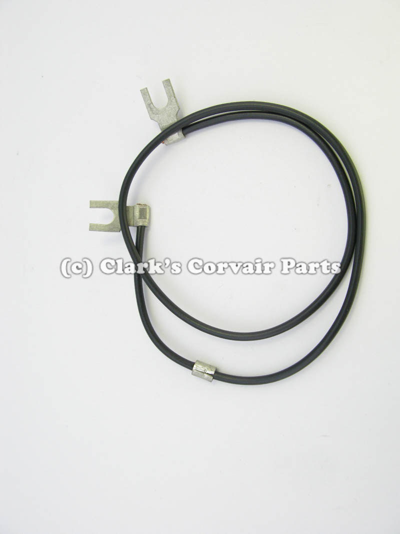
Another common fault is the negative coil terminal wire that connects to the distributor. This wire provides a GROUND connection whenever the ignition points are closed, which energizes the coil primary circuit with voltage at the positive terminal and a GROUND at the negative terminal. If this wire is faulty, the coil will not "see" a ground connection when the points are closed, so the coil will never energize. This short wire between the coil and the distributor flexes internally whenever the vacuum advance moves the breaker plate. Over the years the internal wire strands can break down and provide a faulty or intermittent connection. When the points are closed, you can disconnect the wire from the negative coil terminal and you can use an ohm meter to check for continuity between the wire and chassis ground. If you do not measure a ground through the wire and ignition points, and the distributor housing to GROUND, you will need to determine the cause of the fault. If the wire proves to be faulty it will need to be replaced.

Part number C530: 60-69 DISTRIBUTOR POINT LEAD
Weight: 0 lbs 2 oz
Catalog Pages(s): 75,77(11«),77(19)
Price: $6.50
I have attached a copy of the 1962-63 shop manual supplement (Section 8) for your reference. I hope this circuit explanation and wiring diagrams will help with your troubleshooting. I have also attached sections of the 1965 Corvair Chassis Shop Manual to provide details of the alternator and alternator wiring schematic diagram.
This link will provide you with sources for downloading Corvair shop manuals, supplements, and other useful technical guides and manuals in Adobe Reader (.pdf) format at no cost. Parts sources and other useful links are also included.
Common and Useful Corvair Websites
Corvair Forum
- Attachments
-
- 1965 Corvair Chassis Shop Manual - SECTION 6Y - ENGINE ELECTRICAL.pdf
- 1965 Corvair Chassis Shop Manual - SECTION 6Y - ENGINE ELECTRICAL
- (8.51 MiB) Downloaded 38 times
-
- 1965 Corvair Chassis Shop Manual - SECTION 12 - CHASSIS ELECTRICAL.pdf
- 1965 Corvair Chassis Shop Manual - SECTION 12 - CHASSIS ELECTRICAL
- (6.99 MiB) Downloaded 29 times
-
- 1962-1963 Supplement - Chevrolet Corvair Shop Manual - Section 8 - Electrical Systems.pdf
- 1962-1963 Supplement - Chevrolet Corvair Shop Manual - Section 8 - Electrical Systems
- (2 MiB) Downloaded 46 times
Brad Bodie
Lake Chatuge, North Carolina
 1966 Corvair Corsa Convertible
Lake Chatuge, North Carolina
1966 Corvair Corsa ConvertibleRe: Hello all
Thank you, I am going out of town for the weekend, but will take some pictures of my coil Monday and post them. It threw me off because there is a black wire and a yellow wire with black stripe going to the positive side of the coil as well as a green wire from the regulator and none of that is in the wiring diagrams.
Anyway, I live in central Illinois and have worked on my own vehicles all my life, just never a corvair. If I have a good manual, I can usually get done what I intend to do as far as getting things working as long as I have the time. If I have to have the vehicle to get to work the next day, then things never go right, but that's another story.
Thank you for your help Brad, I will be back Monday and give better info and some pictures.
-
millpondmonster
- Posts: 4
- Joined: Sat Nov 15, 2014 12:25 pm
Re: Hello all
An easy way to tell if you have a internally regulated alternator or externally regulated alternator, is to look at the wiring that plugs into it. If the plug has the wire's standing on edge, side by side like this....I I.... with a square casing, it is externally regulated.
If they are laying flat, side by side like this... _ _ ... with a flat casing, it is internally regulated. Also it may only have a "single hot wire only" coming to it from the battery, that one will also be internally regulated.
If they are laying flat, side by side like this... _ _ ... with a flat casing, it is internally regulated. Also it may only have a "single hot wire only" coming to it from the battery, that one will also be internally regulated.
Re: Hello all
Okay, I got back today and thought I'd post those pictures, but I can't seem to get there. I got one to show in the preview but was unable to upload the other three. How do I go about putting them on here?
Re: Hello all
Okay, last night I didn't take the time to research it very well, but here it is... I started to check out the 1965 shop manual, I'm going to look at it closer as soon as I post this. Thank you again.
- Attachments
-
- I'm not sure what the brown wire that's cut goes to...
-
- The engine wiring harness, I took it apart and pushed the connectors through one at a time and cleaned them up. Eventually I will replace it, but it has continuity across the connector. I was suspicious of it because of the stripped spot on either side of the connector on the black wire going to the alternator.
-
- The top yellow wire goes to the top yellow wire on the alternator and the bottom yellow wire is the one on the alternator connected at the same point as the black wire. The green wire is the one connected to the positive side of the coil primary along with the yellow/black stripe wire and the black wire. There was nothing connected to the fourth position on the regulator.
-
- I'm not sure, is the black wire with the cloth like covering the resistor wire in the diagram? I replaced the coil thinking it was an inexpensive part that probably would need changed out anyway along with the points and condenser.
-
flat6_musik
- Posts: 2659
- Joined: Sun Apr 04, 2010 10:03 am
- Location: Hesperia, CA
Re: Hello all
Try getting a voltmeter (or at least a test light) on the "+" side of that coil, with the key on and also while somebody is cranking it. I'd start there. There's a possibility that those wiring harness connectors aren't delivering the current too, due to years of corrosion.