NMvair --- Your "alternator" guy said wiring the terminal #2 to the battery would result in a "drain". While technically true is is so minor as to be insignificant!!!! The GM/Delco 10SI circuit has been used for decades and this has never been a problem. In fact the battery will discharge on it's own faster. That said I've run into a few aftermarket "Hi-Output" alternators that are poorly designed. Time and again I say "The DELCO engineers knew what they were doing".
I have to agree with Brad that you may be "in over your head with the Stinger distributor". The 140HP engine with a Powerglide used a unique distributor curve. Years ago a fellow in our club had an EM wagon with a 140HP and Powerglide. It ran awful and pinged. It did not have the correct 140HP Powerglide distributor installed.
I looked at the distributor timing curves and found the basic 65/66 110HP stock distributor curve was very close. I had a good used 110HP distributor #1110319 that I gave him. I suggested using the 14degree BTDC static timing vs. the 140HP's 18 degrees BTDC. If it worked well he could try advancing the timing until he got ping and back off two degrees.
He installed the distributor (1110319) set the timing to 14degrees BTDC and the his car ran well, not bogging, no pining. He said he was very happy with the performance and left it at 14degrees BTDC.
I'll add that a few folks initially argued my solution would not work well and it was just a matter of correctly setting up the initial timing of the distributor he had. After the fellow reported the 110HP distributor and 14 degree BTDC worked well that put an end to discussion.
Finally - Seth Emerson was good at setting up the HEI distributors IF it was bought from him!! Many were not bought form Seth and it is not and it not fair to Seth to "fix" something he did not sell.
Initially I set up an ignition with stock points and a proper DELCO distributor that is in good mechanical condition. If folks want an electronic ignition the Pertronix Ignitor (NOT Ignitor II), or FAST XR700 work well WITH THE STOCK BALLAST AND COIL!!! If you do not have a good 140HP engine stock coil, then a new quality coil for a 1965 Chevy Impala 283c.i. V8 works fine. More than adequate and reliable. Only need for more advanced ignition systems in on the Corvair turbo charged engines.
Melting wires, simple question
-
bbodie52

- Corvair of the Month

- Posts: 11937
- Joined: Mon Aug 06, 2012 12:33 pm
- Location: Lake Chatuge Hayesville, NC
- Contact:
Re: Melting wires, simple question

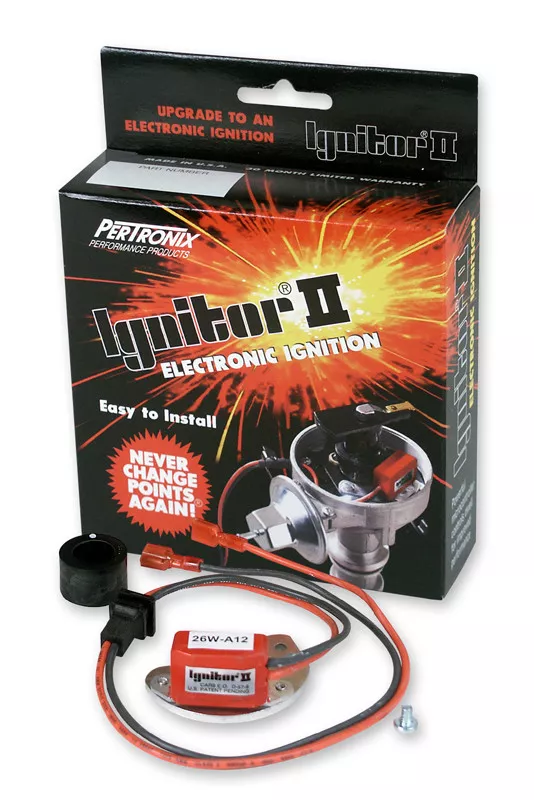
The Pertronix Ignitor II has been known to have some sensor problems with managing a slow idle, such as found with a 6-cylinder Corvair running a Powerglide automatic transmission in DRIVE. I believe the problem appears when the idle speed drops too low for the Pertronix Ignitor II electronic module to manage the slow repetition of the magnetic sensor pulses that occur with a six cylinder engine at idle, while loaded by an automatic transmission in DRIVE. The engine may idle OK with a manual transmission, but with an automatic transmission in DRIVE the additional load from the fluid coupling (torque convertor) slows the engine even more. The ignition system may begin to skip every other pulse, causing an ignition system misfire. This may show up with the engine dying when you shift a properly idling engine from NEUTRAL to DRIVE. The load of the torque converter may slow the engine to the point that the Pertronix unit begins to malfunction. The problem is not present in the Pertronix Ignitor I, the FAST (Crane Cams) XR700 or XR3000, or the Stinger electronic distributor marketed by Performance Corvairs (Seth Emerson).
I believe that the Pertronix Ignitor I version could be damaged by leaving the key in the ON position without the engine running. The FAST/Crane Cams XR700 displays none of these problems. Both Pertronix modules prefer a full 12 VDC power source — bypassing the factory integrated resistor wire. The FAST XR700, however, was specifically designed for the electronics module to be powered by a voltage that has been reduced by the presence of a ballast resistor. Continuous voltage fed to the ignition coil with an external ballast resistor will be only about 7 VDC, instead of 12 VDC or more. The FAST X700 electronic module will begin to overheat if powered continuously by full battery voltage of 12 VDC or more.
The correct wiring configuration for the Pertronix electronic components, or the FAST electronic components, are covered in detail in the installation instructions. It is very important for the installation instructions to be fully understood and followed so that the resulting ignition system "upgrade" will run properly.
Ted in Atlanta has a lot of professional Corvair experience. I remember his recommendation...
terribleted wrote:...I love my Crane ignitions. I have only ever seen one that had failed. Something I can not say about the Pertronix units where failure is somewhat common from what I have seen.
Corvair guy since 1982. I have personally restored at least 20 Vairs, many of them restored ground up. Full time restoration tech and mechanic. https://www.facebook.com/tedsautorestoration
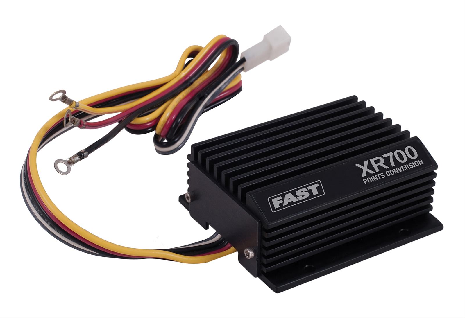
NOTE: THE CRANE CAMS SYSTEM IS NOW MARKETED AS A FAST XR700, DROPPING THE CRANE CAMS NAME
FAST 700-0226 XR-700 Points-to-Electronic Ignition Conversion Kit for Domestic 4, 6 and 8 Cylinder Engines and VW/Bosch 009 Distributors

XR3000 Ignition For Domestic 4, 6 And 8 Cylinder Applications


Brad Bodie
Lake Chatuge, North Carolina
 1966 Corvair Corsa Convertible
Lake Chatuge, North Carolina
1966 Corvair Corsa ConvertibleRe: Melting wires, simple question
I now Brad means well, but the following statement he made has issues:
Both Pertronix modules prefer a full 12 VDC power source — bypassing the factory integrated resistor wire. The FAST XR700, however, was specifically designed for the electronics module to be powered by a voltage that has been reduced by the presence of a ballast resistor. Continuous voltage fed to the ignition coil with an external ballast resistor will be only about 7 VDC, instead of 12 VDC or more. The FAST X700 electronic module will begin to overheat if powered continuously by full battery voltage of 12 VDC or more.
References to module supply voltage and coil supply voltage have been mixed up.
While many connect the Petronix Ignitor power input (not Ignitor II) off the coil "+" terminal if is not the best source of "clean" power and should be connected to the the full ignition voltage BEFORE the ballast. The FAST XR700 has a robust power input module that will run off the coil "+" terminal. Note the coil "+" terminal voltage is NOT a constant 7VDC! In fact an oscilloscope will show a square wave (engine running) with a maximum voltage of about 14VDC (points or switch open) and a minimum voltage of about 7VDC (points or switch closed) which is about an average of 11VDC which many observe with a basic DMM.
BOTH the Petronix Ignitor and FAST XR700 require a ballast and coil primary resistance total that IS NOT LESS than 3.0 ohms to prevent either the ignitor or FAST XR700 from overheating!! The overheating issue is the amperage through the coil, NOT the power supply input voltages.
Yes you can run a 3.0 ohm coil without the ballast, but WHY? The original GM/DELCO system by-passes the ballast to supply full system voltage to the coil when the starter is engaged (starter running lowers system voltage) to prevent poor ignition spark during starting, when the starter disengages coil voltage is supplied via the ballast. A great system used in GM cars for decades.
Re: Melting wires, simple question
It's all very interesting. I got the ignition from Raffy a few years back. I'm thinking it was a Stinger. Since instructions said run a 3ohm coil, that's what I feel like I should do. But the 1 Ohm coil is the one that came with it. If it's wrong........?
Re: Melting wires, simple question
Somewhere in the commentary, Seth Emerson, who originally sold the Stinger, stated that due to electronic module failures he recommended using a 3 ohm coil, but YES originally the Stinger was designed for a low impedance coil of about 1.0 ohm.
The Stinger used the basic GM HEI design (patent expired long ago), but a lot of aftermarket HEI components are inferior. I've mentioned a buddy with a SBC had all kinds of ignition problems with his HEI "copy". I looked at it and the spark was sub-par. He finally went to a company known for quality HEI components and installed them. All his problems went away! AFAIK Seth was the only one who offered a kit to modify the Stinger distributor curve.
The story I read about the Stinger said the company that made the Stinger wanted to paid to give Seth exclusive sales rights and Seth declined. After that the Stinger showed up on a lot of online sites undercutting Seth's prices, but offered ZERO support. The cheap "(&*()*^(*&)" who bought them instead of buying from Seth had the nerve to call Seth to fix things when they had problems. Then Seth simply backed away from the Stinger. Just what I read - may not be true.
Re: Melting wires, simple question
As long as we're having a discussion...
66vairguy wrote:Note the coil "+" terminal voltage is NOT a constant 7VDC! In fact an oscilloscope will show a square wave (engine running) with a maximum voltage of about 14VDC (points or switch open) and a minimum voltage of about 7VDC (points or switch closed) which is about an average of 11VDC which many observe with a basic DMM."
Craig replies: It's a pretty complicated waveform including some higher voltage oscillation that mirrors coil output as the "points" open, plug fires, and the LC circuit decays.
DMMs sample voltage at intervals and any given sample can be anywhere on this complex voltage trace. In my experience, DMM displays flash random numbers as they sample rather than averaging so they don't provide a stable or accurate number. An analog meter provides a steady but still inaccurate reading. The only way to accurately measure coil input voltage is with the engine off and coil (-) briefly shorted to ground for the measurement.
66vairguy wrote:Note the coil "+" terminal voltage is NOT a constant 7VDC! In fact an oscilloscope will show a square wave (engine running) with a maximum voltage of about 14VDC (points or switch open) and a minimum voltage of about 7VDC (points or switch closed) which is about an average of 11VDC which many observe with a basic DMM."
Craig replies: It's a pretty complicated waveform including some higher voltage oscillation that mirrors coil output as the "points" open, plug fires, and the LC circuit decays.
'61 140 PG Rampside
'66 Rear Alum V8 4-dr
'60 Monza PG coupe (sold, sniff, sniff)
'66 Corsa Fitch Sprint Conv. (First car 1971, recently repurchased)
'66 Rear Alum V8 4-dr
'60 Monza PG coupe (sold, sniff, sniff)
'66 Corsa Fitch Sprint Conv. (First car 1971, recently repurchased)
Re: Melting wires, simple question
You are correct. I was trying to keep it simple. Surprisingly even the moderately priced DMMs do a fair job of automatically averaging now. Even some of the cheaper DMMs will average on the VAC mode. When I get a call or see someone post "The DMM reads 11 volts and I was told it should be about 6 volts" it is because they were checking the coil "+" terminal with the engine running.cnicol wrote: ↑Thu Apr 25, 2024 6:25 pm As long as we're having a discussion...
66vairguy wrote:Note the coil "+" terminal voltage is NOT a constant 7VDC! In fact an oscilloscope will show a square wave (engine running) with a maximum voltage of about 14VDC (points or switch open) and a minimum voltage of about 7VDC (points or switch closed) which is about an average of 11VDC which many observe with a basic DMM."
Craig replies: It's a pretty complicated waveform including some higher voltage oscillation that mirrors coil output as the "points" open, plug fires, and the LC circuit decays.
Coil Primary Voltage.JPG
DMMs sample voltage at intervals and any given sample can be anywhere on this complex voltage trace. In my experience, DMM displays flash random numbers as they sample rather than averaging so they don't provide a stable or accurate number. An analog meter provides a steady but still inaccurate reading. The only way to accurately measure coil input voltage is with the engine off and coil (-) briefly shorted to ground for the measurement.
Yes the best way to test voltage drop at the ballast is static measurement and I often suggest it since most DMMs do a poor job of measuring less than 5 ohms. Problem with measuring the voltage is with the engine off the system voltage is about 12.5 VDC and versus about 14.5 when the engine runs. That changes the numbers. Bottom line --- for Corvair the ratio is 1.8 ohms (ballast) divided by 3.1 ohms (total) equals 0.58 times system voltage is voltage drop across the ballast WITH THE POINTS CLOSED. At 12.5 you'll see about 5.3 VDC at the coil "+" terminal and at 14.5 VDC you'll see about 6.1 VDC.
That is assuming the original coil primary resistance of about 1.3 ohms. Sometimes replacement coils are about 1.5 ohms.
-
Frank DuVal

- Posts: 445
- Joined: Wed Dec 09, 2009 4:58 pm
Re: Melting wires, simple question
1. All the Pertronix installations I have worked on (never installed one on my cars) have been the Original Pertronix (aka Pertronix I, didn't come out as Pertronix I, just Pertronix, since there was only one back then!  ) with the GM resistance wire in the circuit.
  They work GREAT! wired this way.
  This is why I do not understand why people keep saying otherwise. Lon sold thousands and never said to bypass the resistance wire.
2. Great picture, Craig. The voltage does rise up when the coil fires, as the negative connection of the high voltage winding is through the points/capacitor parallel circuit. Years ago I thought the negative (I am speaking of negative ground automotive systems, positive ground just reverse all relationships... ) end of the high voltage winding was connected to the steel can of the coil, and grounded through the coil bracket. It was surprising to find out there is no connection from either coil winding to the steel can!
2. Great picture, Craig. The voltage does rise up when the coil fires, as the negative connection of the high voltage winding is through the points/capacitor parallel circuit. Years ago I thought the negative (I am speaking of negative ground automotive systems, positive ground just reverse all relationships...
 ) end of the high voltage winding was connected to the steel can of the coil, and grounded through the coil bracket. It was surprising to find out there is no connection from either coil winding to the steel can!
 Frank DuVal
Fredericksburg, VA
Hey look, blue background! 


Fredericksburg, VA
Hey look, blue background!


Re: Melting wires, simple question
Good comments. When Pertronix came out with the Ignitor II and low impedence Flamethrower coils "the train went off the tracks". That is when I started seeing Corvairs with mis-wired and mis-matched Pertronix parts. Some done by owners, some done by mechanics. After talking to folks I realized the Pertronix instructions and catalog are too vague and sometimes incorrect!Frank DuVal wrote: ↑Thu Apr 25, 2024 8:24 pm 1. All the Pertronix installations I have worked on (never installed one on my cars) have been the Original Pertronix (aka Pertronix I, didn't come out as Pertronix I, just Pertronix, since there was only one back then!
2. Great picture, Craig. The voltage does rise up when the coil fires, as the negative connection of the high voltage winding is through the points/capacitor parallel circuit. Years ago I thought the negative (I am speaking of negative ground automotive systems, positive ground just reverse all relationships...
It not easy going against the local "mechanic" or folks "beliefs". Eventually good results gave me credibility. I am not in "business", just retired and like to help out local Corvair members keep their cars on the road. Then again a smart Alec friend likes to say "Help is only worth what it costs someone and you do it for free!".
Re: Melting wires, simple question
The Pertronix site states the Pertronix (1) operates within a 9-12 volt range. For those cars that us a ballast resistor there should be no reason not to use the INPUT side of the resistor (which nominally should be 12 volts). Unfortunately I think a lot of people unknowingly use the OUTPUT of the resistor that drops the voltage to an "iffy" level to power the Pertronix. The "iffy-ness" being the condition of the battery, alternator/generator and the affect of heat on all the components. For some it works..., and for others not. But why take the chance? Using 12 volts off the ignition switch rules out voltage that MIGHT drop to a critical level.
In a car with a resistor wire where there is no in/out point easily tapped I would always run the Pertronix 1 on a separate, switched, nominal 12 volt wire. In my Sunbeam Tiger world there were people who had scores of problems with the Pertronix 1 unless they ran the 12 volts directly to the device. My own experience with a Pertronix 1 is on a SBC, I run 12 volts off the ignition key and have never had a problem.
Lastly, while it wasn't stated here (at least not yet) the Pertronix doesn't send + (positive) voltage to the coil to make it fire. It works just like points in that it makes and breaks a connection to GROUND. Thus the voltage to the COIL needs be whatever the COIL manufacture recommends and that is set correctly with the ballast resistor (or wire). And the voltage for the Pertronix needs to be what they recommend. In the end it is really TWO separate systems that interact and need their respective, proper voltages.
'61 Lakewood in a coma for 50 years - now has a pulse
-
bbodie52
- Corvair of the Month
- Posts: 11937
- Joined: Mon Aug 06, 2012 12:33 pm
- Location: Lake Chatuge Hayesville, NC
- Contact:
Re: Melting wires, simple question

bbodie52 wrote: » Wed Dec 20, 2023 4:12 pm
Both the FAST and Pertronix systems need a source of voltage to power the electronic module. The most-convenient source for power is the ignition coil positive terminal.
Allison/Crane Cams/FAST knew that the voltage available at the ignition coil positive terminal was not normal vehicle 12-14 VDC power. The vehicle's ballast resistor was designed to drop that voltage down to only about 6-7 VDC. The FAST XR700 electronics design took that into consideration, and the designers built the XR700 to operate correctly using only 6-7 VDC as it's power source. In fact, the instructions cautions about removing the ballast resistor from the supply circuit, as this will cause the XR700 to overheat and begin to malfunction if it is powered by a full nominal 12 VDC source! So, with the XR700 module the ballast resistor wire is retained and the Delco 1.42 ohm coil, or an aftermarket 1.5 ohm coil continues to be powered by a nominal 6-7 VDC power source that is reduced by the original ballast resistor wire. The FAST XR700 module was engineered to take that into account.
HOWEVER, the Pertronix Ignitor or Ignitor II modules were designed to run on full 12-14 VDC vehicle power. The voltage that is reduced by the ballast resistor wire is too low. It is at or slightly below the minimum threshold that the Pertronix modules can tolerate. in some cases the Pertronix Ignitor or Ignitor ii may work, and in some cases it may begin to malfunction if the voltage drops so low that the electronic module may malfunction.
The solution that Pertronix decided to adopt was to recommend elimination of the ballast resistor wire from the vehicle ignition circuit. This would provide a full 12-14 VDC power to the Ignitor or Ignitor II when tapping its power from the ignition coil positive terminal.
To keep the ignition coil internal heat down, Pertronix offers two solutions...
1. Power everything without an external ballast resistor, using full 12-14 VDC power. To do this with a six cylinder engine, they recommend switching to a 3.0 ohm coil, which is considered to be optimum for a four or six-cylinder engine and its associated longer coil primary charging cycles related to a coil supporting fewer engine cylinders. (With an original Delco coil, the total primary coil resistance is 1.42 ohms plus 1.8 ohms from the external ballast resistor... 3.22 ohms!) If your installation eliminates the ballast resistor, the Delco coil would run hot, but switching to a Pertronix Flame-Thrower 3.0 ohm coil would bring the coil resistance back down to a nominal 3.0 ohms — keeping the 3.0 ohm Pertronix internal heat buildup under control, while still providing the external Pertronix Ignitor module with the desired nominal 12-14 VDC power for its electronic module!
2. The other way to handle this, if you retain a Delco 1.42 ohm coil, is to wire things up so that the Pertronix ignitor receives power from a bypassed ballast resistor, while the Delco coil gets its power via the original 1.8 ohm ballast resistor wire. This keeps the total coil primary resistance around 3.0 ohms (1.28 ohms to 1.42 ohms (coil) + 1.8 ohms (ballast resistor wire), while tapping before the ballast resistor wire to supply the higher voltage needed by the Pertronix Ignitor module. This is depicted in the final wiring diagram above.
LEFT-CLICK THE IMAGE TO ENLARGE FOR BETTER VIEWING. CLICK A SECOND TIME FOR MAXIMUM ENLARGEMENT...
- Corvair 12V Switched Tap Location
Brad Bodie
Lake Chatuge, North Carolina
1966 Corvair Corsa Convertible
Lake Chatuge, North Carolina
1966 Corvair Corsa Convertible-
Frank DuVal
- Posts: 445
- Joined: Wed Dec 09, 2009 4:58 pm
Re: Melting wires, simple question
As I said, my experience with the first Pertronix (aka Pertronix I) is simple. Wire to coil and ground. Don't rewire anything. Don't reinvent the wheel. Don't replace the GM coil (they are hardly ever bad). Leave resistance wire in place. Drive happy!
Or just use points. I have lots of points and rebuild the points plates.
Or just use points. I have lots of points and rebuild the points plates.
Frank DuVal
Fredericksburg, VA
Hey look, blue background!
Fredericksburg, VA
Hey look, blue background!
Re: Melting wires, simple question
You make a good argument. However there is another issue. Wiring the Ignitor power input to the coil "+" terminal exposes it to a lot of "electrical noise" from the coil that can damage the Ignitor circuit. The ballast wire acts as a damper so hooking to the ignition voltage before the ballast wire is preferred and the way I've always done it.Wittsend wrote: ↑Fri Apr 26, 2024 9:38 am The Pertronix site states the Pertronix (1) operates within a 9-12 volt range. For those cars that us a ballast resistor there should be no reason not to use the INPUT side of the resistor (which nominally should be 12 volts). Unfortunately I think a lot of people unknowingly use the OUTPUT of the resistor that drops the voltage to an "iffy" level to power the Pertronix. The "iffy-ness" being the condition of the battery, alternator/generator and the affect of heat on all the components. For some it works..., and for others not. But why take the chance? Using 12 volts off the ignition switch rules out voltage that MIGHT drop to a critical level.
So why will the FAST XR700 work powered from the coil "+" terminal? The XR700 has a robust power input filter system to eliminate "electrical noise" from damaging the control circuits, or I should say the original version did. Not sure if FAST has made any changes.
-
joelsplace
- Posts: 2031
- Joined: Wed Oct 13, 2010 12:51 pm
- Location: Northlake, TX
Re: Melting wires, simple question
Put a capacitor on the + side of the coil.
157 Corvairs, 5 Ultravans and counting
Northlake, TX
Northlake, TX