67 engine dies when warm

All Models and Years
User avatar
bbodie52
Corvair of the Month
Posts: 11981
Joined: Mon Aug 06, 2012 12:33 pm
Location: Lake Chatuge Hayesville, NC
Contact:

Re: 67 engine dies when warm

Post by bbodie52 »

Image
:link: https://pertronixbrands.com/products/pe ... -ohm-black
PERTRONIX 45011 FLAME-THROWER II COIL 45,000 VOLT 0.6 OHM BLACK

Image

This is definitely the wrong coil for the Corvair. It cannot be used wit ignition points or a conventional electronic ignition like the XR700, although the XR3000 can handle the ultra-high coil primary current draw. The high output voltage of the secondary (45,000 volts) is way to much overkill for the low RPM, low compression ratio Corvair engine. The installation of the Flamethrower II coil would demand removal/bypass of the ballast resistor wire, so whoever installed the Pertronix Flamethrower II on the Corvair may have modified/bypassed/removed the ballast resistor wire. Such a modification would not work with the FAST/Crane Cams XR700. The XR700 would be powered by too much battery voltage, and the current draw of the Pertronix Flamethrower II would likely damage or destroy the XR700 output switching transistor circuit.
Brad Bodie
Lake Chatuge, North Carolina
Image 1966 Corvair Corsa Convertible
67monza
Posts: 32
Joined: Mon Nov 07, 2022 5:45 pm
Location: lynchburg, virginia, usa

Re: 67 engine dies when warm

Post by 67monza »

Just my 2 cents... All of the above is why I stick with points. Personally, I'd convert back to all stock including standard cheap generic stock coil. It'll set you back about $25 US to do so. Then just do the simple test to confirm your resistor wire is resisting. Making someone else's "creativity" work is more work.
67 Coupe Powerglide, Lynchburg, VA
66vairguy
Posts: 4874
Joined: Tue Dec 21, 2010 3:44 pm

Re: 67 engine dies when warm

Post by 66vairguy »

67monza wrote: Thu Mar 30, 2023 1:09 pm Just my 2 cents... All of the above is why I stick with points. Personally, I'd convert back to all stock including standard cheap generic stock coil. It'll set you back about $25 US to do so. Then just do the simple test to confirm your resistor wire is resisting. Making someone else's "creativity" work is more work.
I can appreciate that. That said, the original Corvair ignition coil is NOT available. Today the only companies that make mechanical points are small off shore places and the quality is hit and miss. I'll add that I do install points whenever I'm trouble shooting a difficult ignition problem.

After some research years ago, I now install a QUALITY (usually special order, cheap coils don't last) coil for a 1965 Chevrolet Impala with the base V8 (283c.i.). It is used on all the V8 Chevies, except a few H.O. engines. It is as close as you'll get to the good coil used on the 140HP engines. I drive it with a basic Petronix I or the FAST (Crane) XR-700 using the stock ballast wire. So far no issues.

All the hype around hi-out put coils is misleading. Except for ultra high compression competition engines, and hi boost turbo units the basic Chevy V8 ignition coil is more than adequate for spark plugs gaped per the shop manual spec. 0.030".
User avatar
bbodie52
Corvair of the Month
Posts: 11981
Joined: Mon Aug 06, 2012 12:33 pm
Location: Lake Chatuge Hayesville, NC
Contact:

Re: 67 engine dies when warm

Post by bbodie52 »

When redesigning/reengineering your car's ignition system, it is important to carefully read and UNDERSTAND the installation instructions. All of the selected components must be properly installed and compatible with each other. The FAST (Fuel-Air Spark Technology) XR700 is a time-proven and well-engineered ignition system.

ImageImage
This is formerly Allison XR700, then Crane/Allison or Crane XR700, and finally was adopted by FAST as a well-established and tested breakerless ignition system. Click on link to open a 20-page installation instruction in Adobe Reader (.pdf) format. Pages 10-12 cover important information on the electronic module installation.
FAST XR700 & XR3000 Instructions.pdf
FAST XR700 & XR3000 Instructions
(507.24 KiB) Downloaded 12 times
Ted in Atlanta has a lot of professional Corvair experience. I remember his recommendation...
terribleted wrote:...I love my Crane [FAST] ignitions. I have only ever seen one that had failed. Something I can not say about the Pertronix units where failure is somewhat common from what I have seen.

Corvair guy since 1982. I have personally restored at least 20 Vairs, many of them restored ground up. Full time restoration tech and mechanic. https://www.facebook.com/ted.fahrenthold
I honestly see no reason to revert back to 1960s technology ignition points, which begin to wear out the day they are installed. A properly installed FAST XR700 will last for many years and provide maintenance-free and reliable ignition operation. Bypassing the Corvair ballast resistor wire will feed the XR700 too much voltage, and coupling the FAST XR700 to an ultra low primary resistance (0.6 ohm) Pertronix Ignitor II leaves the installation with two major strikes against a successful installation! Too much voltage power will likely overheat the electronics, and the very high current drawn by the Pertronix Ignitor II will quickly destroy the output switching transistor circuit!!

Image
:link: https://ssl.corvair.com/user-cgi/catalo ... ow_page=74
Clark's Corvair Parts wrote:Electronic Ignition Note: All units on this page have been extremely good and long lasting, however, if they fail, it is often “all or nothing” so we suggest you keep your old points and wiring in your car just in case
Assuming that your XR700 module has not been damaged by a faulty installation configuration, please ask here on the Corvair Forum if you have any questions regarding a proper installation with compatible components!
Brad Bodie
Lake Chatuge, North Carolina
Image 1966 Corvair Corsa Convertible
Martin
Posts: 31
Joined: Sun Jan 30, 2022 7:35 am
Location: Frankfurt Germany

Re: 67 engine dies when warm

Post by Martin »

So I went to the car today.
I measured the ballast from the cable harness through the cable which goes to the (+) of the coil (white red at the coil, white at the connector) to the (+) of the coil and the resistance was 2.6 Ohm. After putting a 1.6 ohm ballast between the cable it was 4 Ohm. I assume, the 2.6 ohm is somehow correct? However, the trick with briefly touching the (-) of the coil with ignition on does not work for me. I think the reason for this is my multimeter, which is kind of slow and is not able to show the value quick enough... So, if the 2.6 ohm is fine, I will leave it like it is.
Additionally, I tested the fuel pressure. For this, I put the gauge right at the carb side of the fuel line. I only got my hands on a pressure gauge which scale starts at 3 PSI. However, the reading stayed at this point, meaning I must have <3 PSI fuel pressure. So I guess I have to change the fuel pump...
What would cou recommend. I have an AIRTEX pump right now right behind the tank. I think most of you use the facet pump. Do you install it also behind the tank or in the engine bay (I heard this is not good practice). So this clearly is a problem and I will try to get a Facet pump here in Germany.
66vairguy
Posts: 4874
Joined: Tue Dec 21, 2010 3:44 pm

Re: 67 engine dies when warm

Post by 66vairguy »

Martin wrote: Sun Apr 02, 2023 11:59 am So I went to the car today.
I measured the ballast from the cable harness through the cable which goes to the (+) of the coil (white red at the coil, white at the connector) to the (+) of the coil and the resistance was 2.6 Ohm. After putting a 1.6 ohm ballast between the cable it was 4 Ohm. I assume, the 2.6 ohm is somehow correct? However, the trick with briefly touching the (-) of the coil with ignition on does not work for me. I think the reason for this is my multimeter, which is kind of slow and is not able to show the value quick enough... So, if the 2.6 ohm is fine, I will leave it like it is.
Additionally, I tested the fuel pressure. For this, I put the gauge right at the carb side of the fuel line. I only got my hands on a pressure gauge which scale starts at 3 PSI. However, the reading stayed at this point, meaning I must have <3 PSI fuel pressure. So I guess I have to change the fuel pump...
What would cou recommend. I have an AIRTEX pump right now right behind the tank. I think most of you use the facet pump. Do you install it also behind the tank or in the engine bay (I heard this is not good practice). So this clearly is a problem and I will try to get a Facet pump here in Germany.
Something is wrong. The wire to the coil "+" terminal should be YELLOW and is joined to the RED/WHITE/BLACK wire at the starter wires connector.
Ohm meters don't read accurately (unless they are expensive) for less than 10 ohm. You can remove some error by placing the meter leads together and writing down the value, then subtract that value from the measurement.

A fuel pressure gauge that does not indicate below 3 PSI (I assume you are using a kPa gauge in Europe) is useless. You need a gauge that reads 0 to about 10PSI or 0 to 70kPa for good resolution and accuracy.
Martin
Posts: 31
Joined: Sun Jan 30, 2022 7:35 am
Location: Frankfurt Germany

Re: 67 engine dies when warm

Post by Martin »

Yes, I was also surprised after your message.
There is a yellow wire going to (-) crimped together with a white/red wire which has some textil tape around it. I tracked down that the yellow cable goes to a connector together with a purple cable (quite thick) and after testing all pins in the connector, the white/red seems to go to a white cable in the connector (bigger connector). It's right next to another purple one.
The pressure gauge is actually in PSI. I was a bit confused why someone should measure that high pressures of fuel pressure while neglecting the low reads.. however, I tested it with a digital compressor and set it to 4 PSI and the readings were okay. Therefore, I am confident, that we are dealing with 3 or less PSI. I guess this is not enough right? We should be a 4-5 which would be measureable in the gauge.
User avatar
bbodie52
Corvair of the Month
Posts: 11981
Joined: Mon Aug 06, 2012 12:33 pm
Location: Lake Chatuge Hayesville, NC
Contact:

Re: 67 engine dies when warm

Post by bbodie52 »

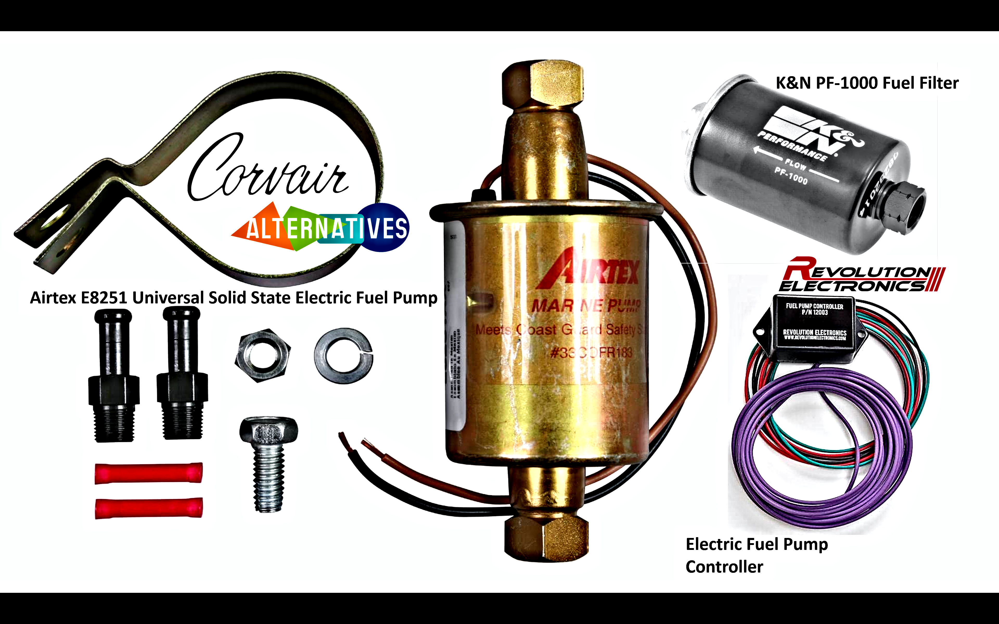
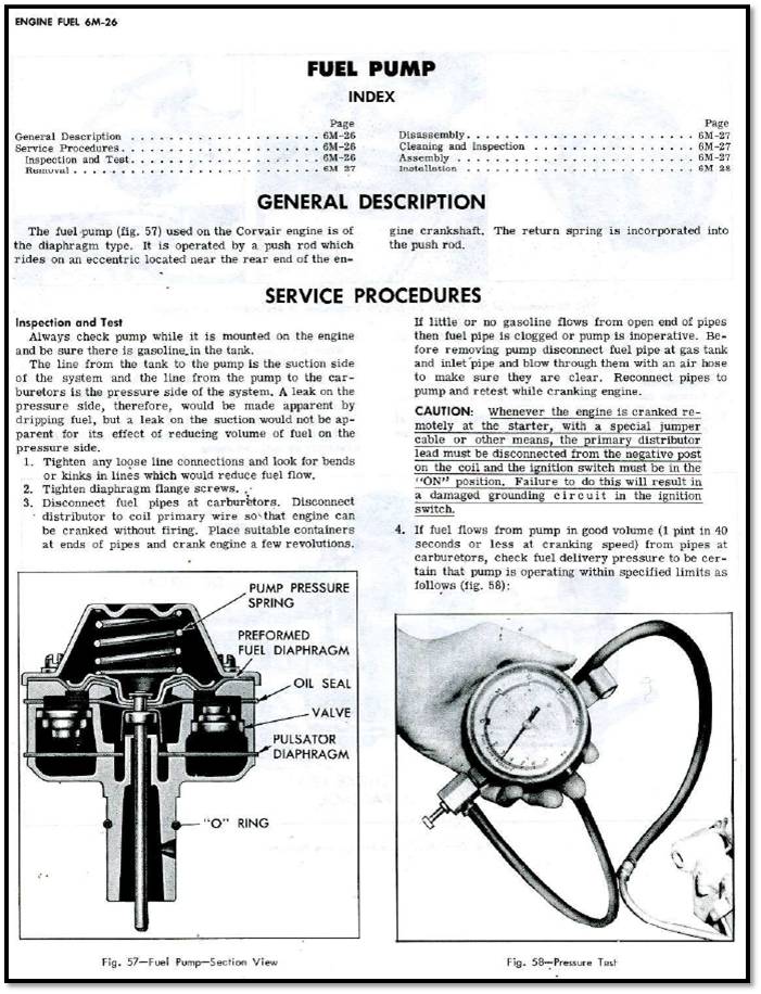
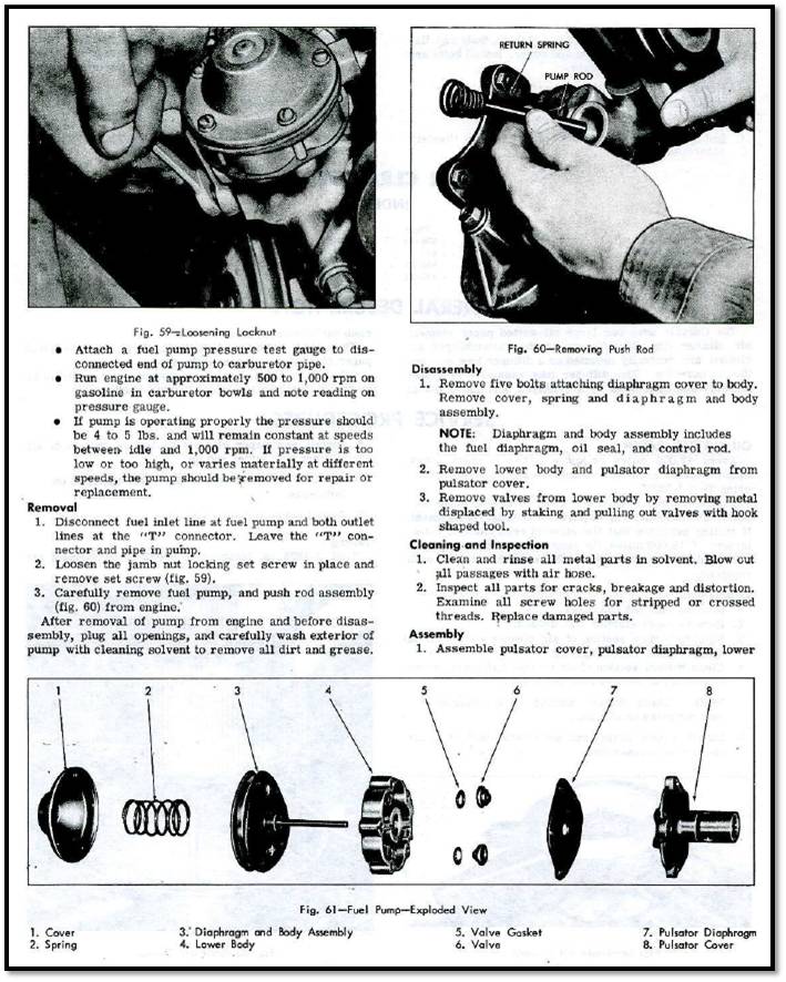
According to the shop manual pages below, the correct fuel pump output pressure should be about 4-5 psi. (3 psi should be sufficient). The volume of fuel being delivered should be about 1 pint in about 40 seconds. Many electric fuel pumps do not do a very good job of pulling fuel long distances from the fuel tank, so the installation instructions usually recommend mounting the electric pump close to the tank outlet, so that gasoline will be gravity-fed to the pump inlet. Then the electric pump can pressurize the fuel and push it long distances to the engine compartment. Unlike most electric pumps, the Corvair mechanical pump was designed to PULL the fuel from the tank at the other end of the vehicle, and then pump it only a short distance to the carburetors.

The Airtex E8251 I selected delivers the correct fuel pressure and fuel volume for the Corvair engine. It is also a fuel pump designed to support marine installations in boats, and because of this the pump also does a good job of pulling fuel long distances. It can be installed near the engine compartment on the Corvair, and does not need to be close to the fuel tank. UNFORTUNATELY IT APPEARS TO HAVE BEEN DISCONTINUED AND IS GENERALLY NO LONGER AVAILABLE. So most electric pumps will require an installation close to the fuel tank. Check the installation instructions for the electric pump you are considering.

Image

ImageImageImage


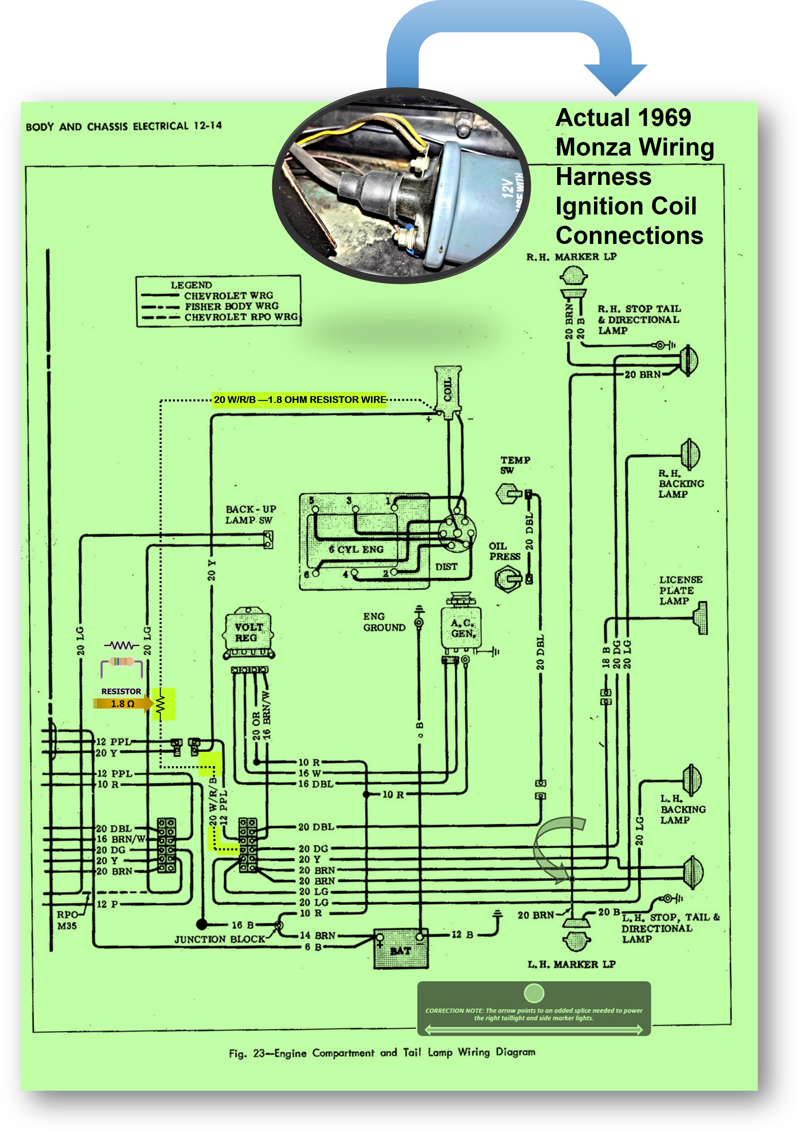
The first diagram below shows two separate wires leading to the ignition coil positive terminal. The wire labeled "20Y" is connected to the starter solenoid. Unless the starter is engaged to crank the engine, this wire is not active and carries no voltage to the ignition coil. It only applies full battery voltage (12.5 VDC) to the ignition coil when the key is rotated to START to crank the engine. This temporarily boosts the voltage feeding the ignition coil to full battery voltage to increase the coil output to the spark plugs to assist in starting the slowly turning cold engine with getting started. When the engine starts the driver releases the key and it returns to the ON position. With the starter solenoid disengaged the higher voltage fed to the ignition coil from the starter solenoid is disconnected, leaving only the lower voltage fed to the coil from the resistor wire (approximately 7VDC). This reduced voltage allows the coil to run at a lower internal temperature, which prolongs the life of the coil. (The reduced voltage produces a weaker spark to the spark plugs, but the weaker spark is sufficient for normal engine operation. The lower voltage also prolongs the life of ignition points switch contacts).


Image

1965 Corvair Monza Full Schematic (Rev. E)
Left-click the image to enlarge it for better viewing or "Pan & Scan"...

While some electronic ignition system designs, like the Pertronix Ignitor, are designed to require a full 12VDC to properly power the electronic circuitry, the engineers who designed the FAST XR700 engineered it to operate properly on the normally reduced 7VDC found on factory installations with a resistor wire or ballast resistor in the circuit. Their intent was to simplify the installation process for the average home mechanic/installer, by allowing the installer to connect the XR700 power wire directly to the ignition coil positive (+) connection, which is already running on a 7VDC power source because of the ballast resistor in the circuit. (If the FAST XR700 required a full 12VDC power source, the installer would have to find a 12VDC power source that was switched on only with the key ON. The XR700 power wire would have to be extended farther from the distributor to connect to a point BEFORE the resistor wire or ballast resistor. Instead, because the XR700 can run on the reduced 7VDC found at the ignition coil, the XR700 power wire can be connected directly to the ignition coil positive terminal, which is near the distributor. HOWEVER, if the ballast resistor wire has been removed or bypassed, a full 12 VDC may be the source voltage found at the ignition coil (sometimes required with the installation of aftermarket high performance coils). The FAST XR700 may initially function with a full 12VDC powering it, but after a short period of overpowered operation the XR700 will likely overheat and will begin to malfunction when powered by 12VDC, instead of the required reduced 7VDC found at the end of a ballast wire circuit.

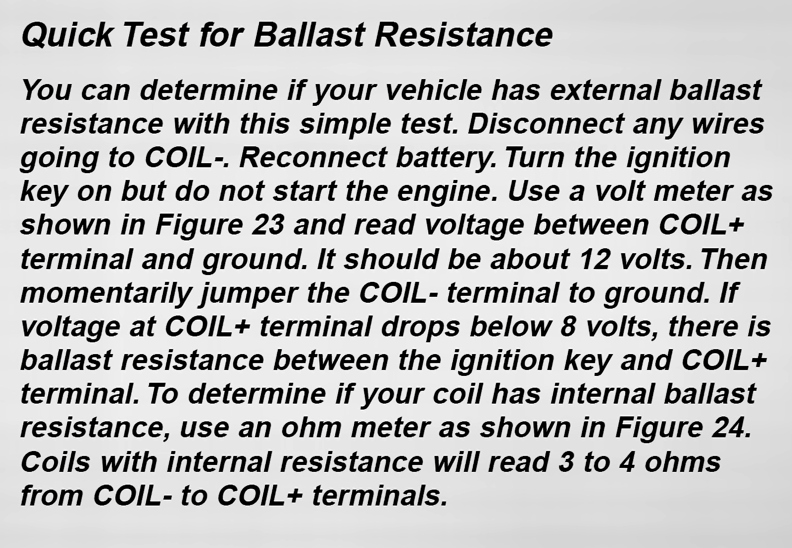
To test and measure the ACTUAL voltage fed to the coil with the key ON, electrical current must be passing through the coil. This only occurs with the ignition points closed, which grounds the negative coil terminal and energizes the coil primary winding (with the key ON). A test of the actual voltage feeding the coil at the positive terminal with the key ON can be done by temporarily grounding the negative coil terminal, turning the key to the ON position, and then measuring the voltage present at the coil positive terminal (the coil must be grounded and conducting electricity through the primary winding to permit an accurate test of the voltage present at the positive terminal. With the key ON, the effect of the ballast resistor wire can only be measured while the coil is grounded and conducting electrical current. When the coil is grounded, the voltage should read the reduced 7VDC voltage caused by the resistor wire in the circuit. If the coil negative terminal is not grounded, no current will be flowing and the voltage at the positive terminal will read a full battery voltage (12VDC).

Image
Brad Bodie
Lake Chatuge, North Carolina
Image 1966 Corvair Corsa Convertible
66vairguy
Posts: 4874
Joined: Tue Dec 21, 2010 3:44 pm

Re: 67 engine dies when warm

Post by 66vairguy »

Martin wrote: Sun Apr 02, 2023 1:58 pm Yes, I was also surprised after your message.
There is a yellow wire going to (-) crimped together with a white/red wire which has some textil tape around it. I tracked down that the yellow cable goes to a connector together with a purple cable (quite thick) and after testing all pins in the connector, the white/red seems to go to a white cable in the connector (bigger connector). It's right next to another purple one.
The pressure gauge is actually in PSI. I was a bit confused why someone should measure that high pressures of fuel pressure while neglecting the low reads.. however, I tested it with a digital compressor and set it to 4 PSI and the readings were okay. Therefore, I am confident, that we are dealing with 3 or less PSI. I guess this is not enough right? We should be a 4-5 which would be measureable in the gauge.
Modern cars typically use fuel injection that requires higher PSI and gauges that measure the higher pressures. Lower PSI gauges are only used on "old" cars now. One issue I find is the incorrect pressure electric fuel pump is installed. There are several ranges and one very confusing problem is the wide range of the pressure specification. For example an electric fuel pump will be rated 4.5 - 7 PSI so folks think "I need at least 4.5 PSI so that is the pump I need" --- NO! For reasons beyond logical thinking --- the pump manufactures like to put huge flow volume numbers on a pump, BUT that lowers the pressure. So at realistic flows the pump creates 7PSI, but at the maximum flow rate the pressure drops to 4.5 PSI. That maximum flow rate will NEVER happen in a Corvair unless the fuel line is cut off so the fuel dumps on the ground! So what pump to use --- one were the higher PSI is in the range of 4 - 5 PSI (ignore the lower maximum flow PSI). I hope this makes sense in the translation.

O.K. The small plug with the large PURPLE wire (engages starter solenoid) and the other connector with the YELLOW wire in the same connector slot as the WHITE/RED/BLACK wire connects to the starter wiring harness plug (that yellow wire should go to the coil "+"). The WHITE/RED/BLACK wire ends up at the large bulkhead connector. Unfortunately GM did not identify these positions with numbers. So the engine harness connector on one side has the WHITE/RED/BLACK wire (with a larger PURPLE wire next to it). If you look at the corresponding connector from the harness that comes from under the car you should see a PINK wire (that is the ignition ON power wire). Your description sounds like someone spliced in a WHITE wire to the resistance WHITE/RED/BLACK wire at he large bulkhead connector and used it to by-pass the WHITE/RED/BLACK resistance wire. Maybe ran the white wire to the coil "+" terminal. What is the wire color at the coild "+" terminal?

Bypassing the WHITE/RED/BLACK wire is done for use with the XR-3000 unit with a 0.6 ohm coil. It sounds like someone made the mistake of wiring for a XR-3000 and installed a XR-700. I see this sort of ignorance all the time when I'm sorting ignition messes. What to do? If I were there (and you bought me a lunch - LOL) I'd sort it out for you. However, you'll have to do some investigation to find out where the WHITE wire goes and correct things so power to the coil "+" positive terminal comes from the small connector at the starter harness (WHITE/RED/BLACK wire and YELLOW wire).

Good luck.
66vairguy
Posts: 4874
Joined: Tue Dec 21, 2010 3:44 pm

Re: 67 engine dies when warm

Post by 66vairguy »

Joel made me think of something. Your car had a FAST XR-700 and the power wire was probably connected to the coil "+" terminal. At this time you said you had removed that and installed the regular electro mechanical points. What happened to the XR-700 power wire?

Basically --- with points you should have a YELLOW wire to the coil "+" terminal and a BLACK wire from the distributor points to the coil "-" terminal.

Regards.
User avatar
bbodie52
Corvair of the Month
Posts: 11981
Joined: Mon Aug 06, 2012 12:33 pm
Location: Lake Chatuge Hayesville, NC
Contact:

Re: 67 engine dies when warm

Post by bbodie52 »

Martin wrote: Sun Apr 02, 2023 1:58 pm Yes, I was also surprised after your message.
There is a yellow wire going to (-) crimped together with a white/red wire which has some textil tape around it. I tracked down that the yellow cable goes to a connector together with a purple cable (quite thick) and after testing all pins in the connector, the white/red seems to go to a white cable in the connector (bigger connector). It's right next to another purple one.
The pressure gauge is actually in PSI. I was a bit confused why someone should measure that high pressures of fuel pressure while neglecting the low reads.. however, I tested it with a digital compressor and set it to 4 PSI and the readings were okay. Therefore, I am confident, that we are dealing with 3 or less PSI. I guess this is not enough right? We should be a 4-5 which would be measureable in the gauge.
The YELLOW wire is connected to the ignition coil positive (+) terminal, and provides ignition power to the coil from two sources: (1) The ballast resistor wire that connects to the main wiring harness. This [WHITE/RED] wire is tied to the wire that originates at the ignition switch, and provides power when the key is in the ON position. The short segment of special [WHITE/RED] resistor wire provides a 1.8 ohm resistance that produces a voltage drop from a nominal 12.5 VDC battery voltage to approximately 7 VDC (to reduce ignition coil internal heat buildup from the primary winding, and to reduce burning/arcing of the ignition points switch contacts each time they open or close). This power feed to the coil positive terminal is continuous as long as the ignition switch is in the ON position. (2) The wire splice at the two-pin connector is also connected to the thin [YELLOW] wire coming from the starter solenoid. (The thick [PURPLE] wire goes from the ignition switch to the starter solenoid. It provides voltage to trigger the starter solenoid when the key is rotated to START). When the starter solenoid is engaged to crank the engine, 12 VDC battery voltage is fed from the solenoid to the thin [YELLOW] wire. The higher 12 VDC battery voltage temporarily overrides the reduced 7 VDC voltage from the resistor wire, and increases the voltage to the coil to boost the spark voltage fed to each spark plug. This helps to promote cold engine starting. When the engine starts, the driver releases the key and the starter solenoid disengages the starter. This also drops the higher voltage feed to the coil, so the coil voltage drops back to the 7 VDC fed to it via the resistor wire.

Ignition System Close-up.jpg
NOTE: On your car, the wire in the diagram labeled B/Y (Black with Yellow stripe) may be solid Yellow in color.
Brad Bodie
Lake Chatuge, North Carolina
Image 1966 Corvair Corsa Convertible
66vairguy
Posts: 4874
Joined: Tue Dec 21, 2010 3:44 pm

Re: 67 engine dies when warm

Post by 66vairguy »

Brad said:"This also drops the higher voltage feed to the coil, so the coil voltage drops back to the 7 VDC fed to it via the resistor wire."

This is ONLY true when the points (or electronic module) connects the coil "-" terminal to ground. When the points open the coil "+" terminal voltage should increase to the system voltage (about 12VDC engine off and about 14VDC engine running)

If you put a meter on the coil "-" terminal while the engine is running it will try to integrate the fluctuating voltages as the points open and close. Usually you get a reading of 9-12 volts depending on the meter.

I sometimes i get calls about taking a voltage reading at the coil "+" terminal with the engine running and asking why it is not about 7VDC.

The ignition coil is a type of transformer. Transformers only work due to changes in the magnetic field caused by voltage and corresponding amperage changes. Points are an early example of DC SWITCHING to run a transformer. This is why early electrical grids stopped using DC and went to AC so transformers could be used. DC to DC switching for transforming voltages was very expensive when scaled up for utilities. Today modern inexpensive integrated DC to DC switching power supplies are common for low power electronics.
Martin
Posts: 31
Joined: Sun Jan 30, 2022 7:35 am
Location: Frankfurt Germany

Re: 67 engine dies when warm

Post by Martin »

Hey again,
great discussion!
Here, you can see an image of the connenctions at the coil. This is now an NGK coil with the ohms, found in the manual.
Image

And here is an image of the connector to the harness that exits the engine bay:
Image

I tested the connections and the yellow wire leaves to a small connector (purple and yellow) that must go to the starter, since the safety switch from the pump is connected at the starter. I hope it is normal, that you can measure a connection between coil (+) and pump safety switch, since these are connected through the starter. The Other cable (this insulated white/red cable) is found on the left side as the white cable, next to the thick purple one. Therefore, it is connected to the thick pink cable. Does this connector look somehow familiar? I have no clue which harness they installed, but apparently the car seemed to run after they put this new harness in (~2014).

PS: I somehow cannot see the pictures, so here are the links:
https://ibb.co/44dpFnN
https://ibb.co/5T5Hx5h
66vairguy
Posts: 4874
Joined: Tue Dec 21, 2010 3:44 pm

Re: 67 engine dies when warm

Post by 66vairguy »

Your pictures were worth the effort. What you have is the revised 1968-69 model harness. I only discovered it was different within the last couple years when I saw a picture at one forum. It took me awhile to confirm the change. For reasons not documented, the resistance wire from the big bulkhead cable was NOT looped back to the starter plug and crimped together with the YELLOW wire as was done in 65 and 66. Instead ONLY a yellow wire was routed from the starter harness connector to the ignition coil "+" terminal. The resistive ballast wire was routed, along with the wiring to the tail lights, to the coils "+" positive terminal. This is were the ballast by-pass (starter engaged) YELLOW wire was joined to the ballast wire - at the coil "+" terminal. Electrically it works the same as the 65 -66 harness routing. It's should NOT be an issue.

There is no evidence this change was done on the 1967 models, but it is possible since it wasn't confirmed for the 68 -69 model years until recently.

I see the wiring to what I assume is the FAST box hooked up. If you have points in the car all the FAST wiring should be disconnected, maybe you have after you took the picture.

You talked about the fuel pump relay. There are a number of "creative schemes" to control the fuel pump power so I can't comment on that.

To summarize: Per your pictures, the PINK wire on the harness connector from the main undercar harness connnects to the white wire on the other side that should be the resistive ballast wire, but I'd expect it to be the same color and insulation (weaved) as at the coil "+" terminal, but that is an ASSUMPTION on my part. I would unplug the main connector to the big engine connector. Next disconnect the ballast (WHITE/RED/BLACK) wire from the coil "+" terminal to do a proper continuity ohm test. If the resistance is off --- I'd carefully open the harness and trace the WHITE wire to determine if it IS the ballast resistive wire, or something someone added to power another device.

You can buy the special harness wrapping tape (it has NO adheasive and stretches to allow bending the harness without breaking wires). Clark's sells it as well as M&H Electrics.

BTW, remove the YELLOW wire at the coil +" terminal, it should measure open (ignition key off and YELLOW wire removed from the coil ", if not it's shorted to something.

Try to get a picture of the PURPLE and YELLOW wires and connector to the starter (should be close to the main connector down around were the throttle rod comes into the engine bay.

Making progress.
Martin
Posts: 31
Joined: Sun Jan 30, 2022 7:35 am
Location: Frankfurt Germany

Re: 67 engine dies when warm

Post by Martin »

Thanks a lot!

I measured the white line to the coil and the whole setup (cable+coil) has now 2.6 ohms. Is that fine or not enough?

Also, here is the picture of the starter: https://ibb.co/GvDjjCc

I have an oil pressure safety switch with one cable going to the starter (-), one the the starter (+) (the new black and red cables) and one from the switch to the pump.

Do you see any problem here?

Best,
Martin
User avatar
Gasman63
Posts: 241
Joined: Sun Feb 12, 2023 5:54 pm

Re: 67 engine dies when warm

Post by Gasman63 »

Sorry i cant help. But im enterested in the oil preasure safety switch. Guessing it dont allow voltage to the coil until you have oil preasure?
1963 Corvair Monza Convertible 140 4 speed.
Colorado Springs :wave:
Post Reply

Return to “Ask your Mechanical Questions here”