There are many "opinions" on how the Corvair Positive Crankcase Ventilation system works. Ranks right up there with opinions about "what oil to use" and "points vs. electronic ignition".
When maintained PCV lowers emissions and has NO negative impact on an engine in good mechanical condition. Another South Coast Corsa article.
Log-in to download .pdf
How the Positive Crankcase Ventilation Works - SCC
How the Positive Crankcase Ventilation Works - SCC
- Attachments
-
- 20210319 Corvair PCV article.pdf
- (122.67 KiB) Downloaded 54 times
-
bbodie52

- Corvair of the Month

- Posts: 11975
- Joined: Mon Aug 06, 2012 12:33 pm
- Location: Lake Chatuge Hayesville, NC
- Contact:
Re: How the Positive Crankcase Ventilation Works - SCC
Corvair Positive Crankcase Ventilation (PCV)
By Bob Nichols
Last Revision March 19, 2021
Positive Crankcase Ventilation (PCV) is often misunderstood. First some basics about crankcase ventilation. Next a function explanation. Finally, a discussion of PCV misconceptions.
When the air fuel mixture is compressed and ignited in the cylinder some combustion gases get by the piston rings into the engine crankcase and must be vented. Originally this was done with a “draft” tube connected to the engine that let crankcase gases vent to the atmosphere. The draft tube was designed to send crankcase gasses down and out along the bottom of the vehicle and hopefully not into the passenger compartment. This
is an “open” crankcase ventilation system.
GM’s military program in the 1940’s devised a “closed” crankcase ventilation system to prevent water from entering the crankcase when a vehicle forded water. After research and testing, a system was developed that was not costly to implement or detrimental to engine operation. It is now referred to as “Positive Crankcase Ventilation” (PCV).
The adoption of PCV to civilian automobiles was in response to a couple of issues:By the late 1950’s GM research laboratories released the design for use by the rest of the automotive industry. Initially required on 1961 vehicles sold in California, by 1964 most vehicles were equipped with a PCV system.
- Luxury automakers were keenly aware of “odors” from the engine compartment that were not acceptable to owners. This was before air conditioning was common.
- By the 1950’s it was recognized that crankcase gases comprised as much as 50% of hydrocarbon emissions from vehicles to the atmosphere! Airborne emissions were becoming a health issue in some areas of the nation.
The Corvair PCV system was implemented in model year 1963. The first design used a spring loaded check valve, often called a “PCV valve”. The 1964 models replaced the PCV valve with a fixed orifice as part of the vacuum balance true. The exception was 1964 and 1965 air conditioned equipped cars which used a PCV valve. The FC models also used a PCV valve system. These vehicles required a low profile dual air cleaner system that used a PCV valve.
So how does the Corvair PCV work? The crankcase gases do not escape to the atmosphere, but are ingested via the intake manifold or carburetors to be burned as part of the air fuel mixture.
The crankcase gasses MUST vent to both the intake manifold and carburetors ( via the air cleaner) so the
carburetor air/fuel mixture is not compromised by varying engine speeds and loads. This may seem complicated, but in fact the system is elegantly simple by design as follows:This allows the air/fuel mixture to remain within optimal parameters during varied engine operations as follows:
- Crankcase gasses are pulled into the intake manifold by vacuum via a metering PCV valve or a fixed orifice in the vacuum balance tube. This results in a constant impact on the air fuel mixtures that can be compensated for by the carburetor design/calibration.
- Variations in the crankcase gasses volume and intake manifold vacuum pressure are compensated for by a path to the air cleaner and carburetors to ensure a proper metered flow into the intake manifold.
- When engine vacuum is high and crankcase gasses volume is low, air from the air cleaner mixes with the crankcase gasses to maintain atmospheric pressure at the input to the PCV valve or fixed orifice.
- When engine vacuum is low and crankcase gases volume is high, the excess crankcase gasses go to the air cleaner to be ingested via the carburetor. This maintains atmospheric pressure at the input to the PCV valve or fixed orifice.
The Corvair PCV system uses metal tubes and hoses to connect the crankcase to both the intake manifold and air cleaner. Refer to the appropriate model year Corvair Chassis Shop Manual for configuration and service procedures. The PCV system should be inspected to ensure the system is not blocked by debris, especially the metering valve or orifice, at every engine oil change interval. Model years 1964 through 1969 Chassis Shop Manuals state the fixed orifice size is 0.062” for all engines except the turbo that has a 0.089” orifice size. NOTE: The 1965 Chassis Shop Manual incorrectly says all engines used a 0.089” fixed orifice size.
- IDLE – Manifold vacuum is HIGH and crankcase gases volume is not adequate enough to meet the flow volume demanded by the PCV valve or fixed orifice. A connection to the air cleaner allows filtered air to flow FROM the carburetor air cleaner to ADD to the gasses FROM the crankcase. This prevents a vacuum from forming in the crankcase, but more importantly, it maintains the proper metered air flow via the PCV valve or fixed orifice into the manifold so the carburetor air and fuel mixture is stable. Refer to figure 1.
- WIDE OPEN THROTTLE – Manifold vacuum is LOW and crankcase gasses volume is greater than can be consumed by the intake manifold metering device. The crankcase gasses not ingested into the intake manifold go TO the air cleaner and are pulled into air drawn into the carburetor(s) and consumed in the cylinder by combustion. The throttle is open enough to produce a positive airflow through the air cleaner to ensure the crankcase gases do not escape out to the atmosphere. Refer to figure 2.
- VARIABLE ENGINE OPERATION/LOAD – The manifold vacuum and crankcase gases volume change in response to; throttle positions between idle and wide open, and varying engine load conditions when driving. This dynamic condition is accommodated by the PCV system dual path from the crankcase to the metered port to the intake manifold and carburetors via the air cleaner.
Misconceptions about the PCV system:
- The engine runs better if the PCV system is removed. FALSE.
- This was a common misconception about early systems due to the combination of PCV with other emissions controls. PCV does not negatively affect engine operation, but the other emissions control systems often did cause poor engine operation!
- A properly functioning PCV reduces emissions and it is irresponsible to disconnect the PCV.
- You don’t have to connect the PCV to both the engine vacuum and air cleaner. FALSE
- This is one of the most confusing issues. The crankcase MUST be connected to both the engine vacuum and air cleaner.
- Why?
- The engine crankcase gasses must be consumed by combustion via the intake manifold vacuum or the carburetor via the air cleaner.
- The engine crankcase and input to the PCV valve, or fixed orifice, must be at the same atmospheric pressure present at the air cleaner for proper PCV operation.
- Without the stock air cleaner, you can connect the PCV tube to a free standing air filter. DANGER
- A popular modification is to remove the original Corvair air cleaner assembly and install an after market air cleaner(s). Under certain engine operations crankcase gasses will be expelled out the free standing air filter and drawn into the engine cooling fan. These gasses contain poisonous carbon monoxide that could enter the heater system when it is operated and find its way to the passenger compartment causing illness or death!!
- It is recommended you use an after market air filter assembly with a PCV hose fitting, or purchase a filter to carburetor adapter with a PCV hose fitting.
- PCV cycles fresh air through the engine to reduce oil temperature. YES AND NO
- This is NOT the primary function of the PCV system, although on some “V” engines it is a minor side effect. It is NOT a function of the Corvair PCV. Some owners have run a PCV hose from the Corvair oil filler tube to the air cleaner to emulate the “V” engine PCV path, but as in some “V” engines it can result in engine oil transfer to the air cleaner assembly at higher RPM. The Corvair engine has a baffle between the crankcase and engine top cover to reduce engine oil ingestion into the PCV system.
- The PCV system requires no maintenance – FALSE.
- Engine crankcase gases contain products that will accumulate in the PCV system. The rate of accumulations depends on engine operation, and the duration of intervals between engine oil changes. When the Corvair was manufactured the service manual recommended an inspection of the PCV system whenever the engine oil is changed. In particular either the PCV valve or vacuum balance tube orifice must be inspected for accumulation of deposits from crankcase gasses. DO NOT damage, or alter the size, of the fixed orifice if it requires cleaning. On vehicles equipped with a PCV valve, it is replaced as needed. The “needed” guidelines for replacement tend to be vague and the typical practice in the 1960’s was to replace the PCV valve at the time of the “tune-up” at 12,000 miles, or once a year – whichever came first. It should be noted the “tune-up” period was more of a default by service departments, not per manufacturer’s guidelines. NOTE: As stated here previously: Model years 1964 through 1969 Chassis Shop Manuals state the fixed orifice size is 0.062” for all engines except the turbo that has a 0.089” orifice size. The 1965 Chassis Shop Manual incorrectly states all engines used a 0.089” fixed orifice size.
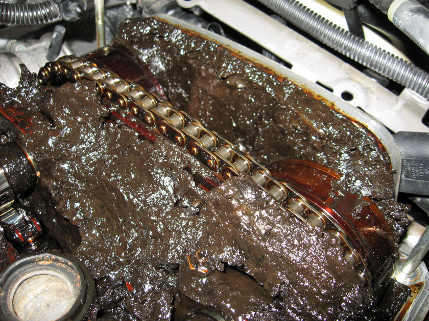
- A note of caution about worn engines. If the piston, ring, and engine cylinders are worn beyond specification, then excess combustion gases into the engine crankcase (called “blow-by”) will results in a mixture of oil and deposits called “sludge” accumulating in the PCV system. Sludge could block portions of the PCV system resulting in poor engine operation and a pressurized engine crankcase causing excessive oil leakage from the engine.
Brad Bodie
Lake Chatuge, North Carolina
 1966 Corvair Corsa Convertible
Lake Chatuge, North Carolina
1966 Corvair Corsa Convertible-
bbodie52
- Corvair of the Month
- Posts: 11975
- Joined: Mon Aug 06, 2012 12:33 pm
- Location: Lake Chatuge Hayesville, NC
- Contact:
Re: How the Positive Crankcase Ventilation Works - SCC
 I copied one of my earlier posts on this subject here to add Corvair-specific illustrations to help visualize the actual Corvair hardware...
Common Custom Air Cleaner PCV Errorsbbodie52 wrote: » Mon Apr 25, 2022 2:26 pm

I have included a lot of background and technical information below, to hopefully help with your understanding of the Positive Crankcase Ventilation system on the Corvair. It is a two mode system that covers all of the engine variables and operating conditions. If you remove the factory standard air filter system, you must retain both the intake manifold vacuum portion (using a PCV Valve or fixed-orifice to manage the airflow) AND the portion that originally connected to the factory air cleaner. This allows your crankcase to breath at low and high RPM, partial throttle and open throttle conditions, and everything in-between. Connecting the portion that originally connected to the factory air filter to an aftermarket custom air cleaner instead (at the custom air filter base, directed into the carburetor throat) will get the job done. It is only necessary to connect that part via hose to an air cleaner on one side primary carburetor. It is not necessary to link it to both sides when two custom air cleaners are installed. (This custom setup is similar to the one shown to be in-use in standard/stock 1963 Corvair passenger cars and in 1963 and later Corvair vans and trucks).
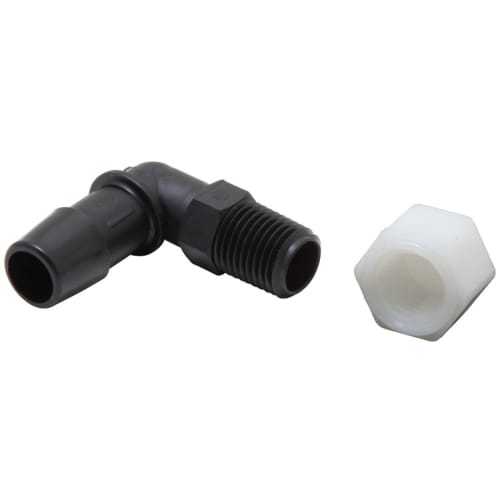
An example of a custom air filter PCV hose fitting is shown below. The first example usually is fitted to a single, large central air cleaner, while the second design is routed into the side of the smaller single one barrel carburetor air cleaner. It is probably more appropriate for a Corvair custom air cleaner that is mounted on one Rochester HV primary carburetor.
85-1120 K&N AIR FILTER VENT KIT
$19.99 USD
https://www.knfilters.com/85-1120-air-f ... 0UQAvD_BwE
bbodie52 wrote: » Sun May 20, 2018 10:21 am
Corvairs were fitted with a simple vacuum balance tube which assists in synchronizing and balancing the performance of the two banks of cylinders. GM engineers felt this tube was necessary to help balance the performance by connecting the intake manifolds together. The vacuum balance tube also provides a connection point for engine accessories that require intake manifold vacuum to operate properly. The Powerglide automatic transmission utilizes a vacuum modulator that depends on the balance tube for its connection to engine intake manifold vacuum. In 1963 the crankcase breather tube (road draft tube) was eliminated and replaced with a Positive Crankcase Ventilation (PCV) system that requires a steady source of engine vacuum to help evacuate crankcase fumes from the engine crankcase. The PCV system utilizes a PCV valve or a fixed orifice to control airflow between the crankcase and the intake manifolds. The PCV system design also requires a hose connection to the air cleaner system, but this should not be confused with the vacuum portion of the PCV system. Do not attempt to connect the vacuum balance tube directly to an air cleaner. Doing so would create a serious vacuum leak that would cause the engine to run with a very lean fuel/air mixture. The PCV valve or fixed orifice (introduced in 1964) is essential to regulate the amount of airflow from the PCV system that bleeds into the vacuum balance tube. If a PCV system exists on your non-turbo engine, the connection to the air cleaner is made on the crankcase side of the tube, which helps the PCV system to provide filtered crankcase pressure relief and to allow excess fumes as some engine speeds to be drawn in through the carburetor intake rather than the intake manifold. If your engine does not have a PCV system it is likely fitted with a road draft tube to allow for crankcase ventilation directly to the outside air. With this early design crankcase ventilation system no connection is made to the vacuum balance tube or the air cleaner.Crankcase Emission Control
The problem of crankcase ventilation has been encountered since the beginning of the automobile because no piston ring, new or old, can have a perfect seal between the piston and the cylinder wall. During running of the engine, the pressure of combustion forces the piston downward, and also the chamber gases past the piston rings and into the crankcase. These outlets are called crankcase vapors, or blow by.
Crankcase vapors contains light hydrocarbons, crankcase oil vapors, and combustion chamber gases. Crankcase oil vapors constitute the light volatile portions of the motor oil, evaporated at engine operating temperature. Combustion chamber gases, which have entered into the crankcase primarily come from the quench area within 0.05 mm to 0.5 mm of the combustion chamber surface. These gases have the same content as the gasoline being used. These gases are unburnt because they are cooled by the relatively low temperature of combustion chamber wall surface. Every time a driver opens the throttle, the rate of flow of blow-by gases to crankcase increases. The blow by gas causes three undesirable problems.
- It destroys the lubricating properties of engine oil.
- It allows the formation of sludge and varnish.
- It helps to form corrosive acids, which damage engine parts.
ROAD DRAFT TUBE systems were around for many years. They were not very efficient or effective at removing piston blowby contaminants from the engine crankcase and valve train area. As a result, engine oil would become badly contaminated if it was not changed very frequently. Engines would develop harmful sludge. The unburned contaminants that did escape into the atmosphere via the road draft tube contributed greatly to the SMOG content in the air. The development of the PVC system was a huge advancement in pollution reduction and engine protection. while causing almost no degradation in engine power, performance, or drivability.
See ENGINE SLUDGE

The illustrations below should help you to visualize the crankcase ventilation system that is in use on your engine. If you have a PCV system on your engine, the crankcase breather side (non-vacuum side) should be connected to the factory air cleaner system or one of the two custom air cleaners on the primary carburetors.. A number of accessory manufacturers provide an appropriate fitting as pictured below. However, if the custom air cleaners you chose are small in diameter, you may have to fabricate an appropriate fitting to match the size of your air cleaner.
Mr. Gasket 2079 PVC Air Cleaner Smog Fitting
Wikipedia wrote:Road draft tube
The first refinement in crankcase ventilation was the road draft tube, which is a pipe running from a high location contiguous to the crankcase (such as the side of the engine block, or the valve cover on an overhead valve engine) down to an open end facing down and located in the vehicle's slipstream. When the vehicle is moving, airflow across the open end of the tube creates a draft that pulls gases out of the crankcase. The high location of the engine end of the pipe minimizes liquid oil loss. An air inlet path to the crankcase, called the breather and often incorporated into the oil filler cap, meant that when a draft was generated at the tube, fresh air swept through the crankcase to clear out the blow-by gases.
The road draft tube, though simple, has shortcomings: it does not function when the vehicle is moving too slowly to create a draft, so postal and other slow-moving delivery vehicles tended to suffer rapid buildup of engine sludge due to poor crankcase ventilation. And non-road vehicles such as boats never generated a draft on the tube, no matter how fast they were going. To remedy this situation manufacturers located the breather air filter in the air stream coming from the engine radiator fan, the manufacturers also modified the breather to incorporate an air scoop to direct the air into the breather filter so that the engine could be ventilated while the car or truck was standing still. The draft tube discharged the crankcase gases, composed largely of unburnt hydrocarbons, directly into the air. This created pollution as well as objectionable odors. Moreover, the draft tube could become clogged with snow or ice, in which case crankcase pressure would build and cause oil leaks and gasket failure.
There is nothing fancy or particularly desirable about the road draft tube. Unless you are concerned about being historically accurate with your car, I would recommend obtaining a 1964 or later PCV system, including the appropriate vacuum balance tube, a fixed orifice design PCV system, and perhaps the newer, redesigned center vent baffle from later models. Upgrading seals your crankcase and prevents dirt from entering, and provides for a positive extraction of fumes and crankcase contaminants to reduce the formation of crankcase sludge. The components you need are not bulky or heavy, and could be obtained from a source like the Corvair Ranch in Gettysburg, Pennsylvania.

[/quote]bbodie52 wrote:
To summarize... the Positive Crankcase Ventilation (PCV) system has TWO ventilation paths between the engine crankcase and the engine INTAKE MANIFOLD. Two paths are needed to allow the PCV system to function at low RPM (closed or partial throttle) settings, when intake manifold vacuum is relatively high, and at open throttle settings, when intake manifold vacuum is low, but air velocity through the carburetor throat (venturi) is high. Piston ring blowby can occur at all engine speeds and allows some fuel/air mixture to leak into the crankcase, building crankcase pressures with contaminated fuel/air vapors. At low engine speeds the high intake manifold vacuum sucks these crankcase vapors through the fixed (metered) orifice or PCV valve and recycles those fumes back through the intake manifold, to be burned in normal combustion chamber activity and sent out of the tail pipe. As engine RPM increases with open throttle action, intake manifold vacuum decreases, so the crankcase fumes take the secondary path via the air cleaner and down the carburetor throat — ultimately ending up in the same place: back in the combustion chamber — to be burned and sent out through the exhaust system.
The piston ring seal in each cylinder is never perfect, so there will always be some blowby past the pistons and into the crankcase. If that blowby is allowed to linger in the crankcase, oil contamination and heat can produce harmful sludge. All the PCV system does is to effectively put the blowby gases back where they belonged in the first place... the combustion chambers! The PCV-routed gases are mixed in small quantities with the normal fuel/air mixture, and the spark plugs set off the burning process and the exhaust system takes care of the rest!

Brad Bodie
Lake Chatuge, North Carolina
1966 Corvair Corsa Convertible
Lake Chatuge, North Carolina
1966 Corvair Corsa ConvertibleRe: How the Positive Crankcase Ventilation Works - SCC
Nice post!! I thought it might be interesting and helpful for some folks to point out a unusual bug that can come about
with the Turbo crankcase ventilation system when converting to EFI that I ran into. In the stock system, oily vapors go into the turbo inlet through the small tube attached to the turbo. Because there is also gasoline and additional air being mixed with these oily vapors, the entire intake system is continually washed of oil. However in going to a EFI system like mine, the intake system is now dry air all the way to the intake ports. After a few months of driving with the EFI, I began noticing oil seeping/sliming up the connection at the turbo/cross over manifold connection. I took the manifold off, and noticed that oil was collecting between the turbo and the manifold. Thinking about this, I realized that there wasnt anything wrong with the carbon seal, and the reason I never saw this before the conversion had everything to do with having dry air going through and not washing these misicule droplets of oil away! The solution was to put an air /oil separator in line with that small tube. It was a really nice modification, as it killed the problem, AND because of the large reduction of oily vapors admitted into engine, reduced (alot) the tendancy to ping, because oil tends to light off from heat, and can start the combustion well before the spark plug lights off the mixture. The other nice benefit is that a lot of crap stays out of the oil!
with the Turbo crankcase ventilation system when converting to EFI that I ran into. In the stock system, oily vapors go into the turbo inlet through the small tube attached to the turbo. Because there is also gasoline and additional air being mixed with these oily vapors, the entire intake system is continually washed of oil. However in going to a EFI system like mine, the intake system is now dry air all the way to the intake ports. After a few months of driving with the EFI, I began noticing oil seeping/sliming up the connection at the turbo/cross over manifold connection. I took the manifold off, and noticed that oil was collecting between the turbo and the manifold. Thinking about this, I realized that there wasnt anything wrong with the carbon seal, and the reason I never saw this before the conversion had everything to do with having dry air going through and not washing these misicule droplets of oil away! The solution was to put an air /oil separator in line with that small tube. It was a really nice modification, as it killed the problem, AND because of the large reduction of oily vapors admitted into engine, reduced (alot) the tendancy to ping, because oil tends to light off from heat, and can start the combustion well before the spark plug lights off the mixture. The other nice benefit is that a lot of crap stays out of the oil!
Re: How the Positive Crankcase Ventilation Works - SCC
Good information. The oil separator is a nice touch and used on some high performance European engines in the 60's and 70's.
My Dad had a 1965 Olds and occasionally he had to travel for business. Every time he drove over 80MPH for a while his Olds would start to smoke! He would take the top off the air cleaner, remove the air filter and wipe out the excess motor oil from around the PCV inlet in the air filter housing. Then the car was fine. If he kept the RPM lower by not driving over 75MPH he never had the issue. The high RPM created an oil fog that blew up the PCV hose to the air cleaner.
I've seen this happen on on other cars of the era.