1960 Monza Coupe
Re: 1960 Monza Coupe
That's one clean tank, inside & out!

Re: 1960 Monza Coupe
I sent you an email. Let me know.
Scott
1960 Monza Coupe
1965 Evening Orchid Corsa Turbo (project)
1961 Rampside (project)
1964 Spyder coupe (patina car, running)
1964 faux Spyder (project/parts car)
1964 Monza (parts car)
1963 Monza (parts car)
1960 Monza Coupe
1965 Evening Orchid Corsa Turbo (project)
1961 Rampside (project)
1964 Spyder coupe (patina car, running)
1964 faux Spyder (project/parts car)
1964 Monza (parts car)
1963 Monza (parts car)
Re: 1960 Monza Coupe
Ok I finally got the car on the road.
- Attachments
-
-
Scott
1960 Monza Coupe
1965 Evening Orchid Corsa Turbo (project)
1961 Rampside (project)
1964 Spyder coupe (patina car, running)
1964 faux Spyder (project/parts car)
1964 Monza (parts car)
1963 Monza (parts car)
1960 Monza Coupe
1965 Evening Orchid Corsa Turbo (project)
1961 Rampside (project)
1964 Spyder coupe (patina car, running)
1964 faux Spyder (project/parts car)
1964 Monza (parts car)
1963 Monza (parts car)
Re: 1960 Monza Coupe
More pics from its first car show.
- Attachments
-
-
Scott
1960 Monza Coupe
1965 Evening Orchid Corsa Turbo (project)
1961 Rampside (project)
1964 Spyder coupe (patina car, running)
1964 faux Spyder (project/parts car)
1964 Monza (parts car)
1963 Monza (parts car)
1960 Monza Coupe
1965 Evening Orchid Corsa Turbo (project)
1961 Rampside (project)
1964 Spyder coupe (patina car, running)
1964 faux Spyder (project/parts car)
1964 Monza (parts car)
1963 Monza (parts car)
Re: 1960 Monza Coupe
Few more
- Attachments
-
-
-
Scott
1960 Monza Coupe
1965 Evening Orchid Corsa Turbo (project)
1961 Rampside (project)
1964 Spyder coupe (patina car, running)
1964 faux Spyder (project/parts car)
1964 Monza (parts car)
1963 Monza (parts car)
1960 Monza Coupe
1965 Evening Orchid Corsa Turbo (project)
1961 Rampside (project)
1964 Spyder coupe (patina car, running)
1964 faux Spyder (project/parts car)
1964 Monza (parts car)
1963 Monza (parts car)


Re: 1960 Monza Coupe
Very nice!!
Dave W. from Gilbert, AZ
66 Corsa 140/4 Yenko Stinger Tribute
66 Corsa 140 Coupe w/factory A/C
65 Monza 4DR 140/PG w/factory A/C
65 Monza 4DR EJ20T/5
64 Greenbrier 110/PG, Standard 6-Door
66 Corsa 140/4 Yenko Stinger Tribute
66 Corsa 140 Coupe w/factory A/C
65 Monza 4DR 140/PG w/factory A/C
65 Monza 4DR EJ20T/5
64 Greenbrier 110/PG, Standard 6-Door
Re: 1960 Monza Coupe
Nice and great photography! I thought it was a scale model in some of your first photos!
-
bbodie52

- Corvair of the Month

- Posts: 12143
- Joined: Mon Aug 06, 2012 12:33 pm
- Location: Lake Chatuge Hayesville, NC
- Contact:
Re: 1960 Monza Coupe
Beautiful engine installation! 


T0927R?
Can't see the last letter in the engine serial number. I'm assuming (with the harmonic balancer) a 1965-68 110hp engine.

This 3 ohm coil is the one recommended by Pertronix for use with 4 or 6 cylinder engines. The 3.0 ohm coil appears to be the one used on your engine. (Pertronix recommends the 1.5 ohm version for 8 cylinder engines). I have read some complaints on the Corvair Forum about poor reliability or short operational lifespan with Pertronix Flamethrower coils, but that could be caused by using a 1.5 ohm coil on a six cylinder engine with a full 12 VDC power source. Reliability may be improved if the appropriate 3.0 ohm coil is used. Also, relocating the coil mount away from the hot cylinder head and mounting the coil on the engine compartment perimeter frame may help to keep heat buildup down in the coil.
I believe the difference in recommended coil primary resistance has something to do with the longer coil charging time periods, or the amount of time the voltage is applied to the coil primary winding before firing each cylinder, with only four or six cylinders in play (fewer distributor cam lobes than an eight cylinder engine). With a 12 VDC power source, the four or six cylinder engine has plenty of time for the coil to build a charge before firing each spark plug, so the 3.0 0hm internal resistance keeps the heat buildup at appropriate levels for the coil. An eight cylinder engine has more firing impulses to provide during each crankshaft rotation, so it needs greater current flow through the primary coil to achieve the desired high voltage output from the secondary winding. This is managed by reducing the primary resistance with an eight cylinder engine to 1.5 ohms to help the coil to keep up with the demand.
The coil is to be wired directly to a 12 VDC source, bypassing any external ballast resistor or resistor wire. If your coil is a 3 ohm model, was the resistor wire in the wiring harness bypassed to provide power? If it was not, the total primary resistance would be too high, at approximately 4.8 ohms with the 1.8 ohm resistor wire in the circuit. This much primary resistance would greatly reduce the coil high-voltage output to the spark plugs. Also, it looks like you may be using a breakerless electronic ignition system in the distributor. If so, what model are you using? Pertronix Ignitor? (Both the Pertronix Flamethrower coil and the Pertronix Ignitor ignition module should be powered by a full 12 VDC source, with no external ballast resistor in the circuit).
Roger Parent throttle linkage? How do you like it?
Mr. Gasket Micro Electric Fuel Pump
4 - 7 PSI - 35 GPH - Gasoline - for carburetor, Part# 12S

Gravity fed type pump with simple two-wire design. Works on 12 Volt negative ground systems only. Includes fittings and mounting hardware along with easy to follow DIY instructions. Pumps require approximately one amp average draw at maximum delivery. Flows 35 GPH (gallons per hour at 4-7 PSI (pounds per square inch). Universal design for most domestic 4, 6, & 8-cylinder carburetor applications.
Features:
Mr. Gasket Micro Electric Fuel Pump
2 - 3.5 PSI - 28 GPH - Gasoline - For Carburetor, Part# 42S

Overall, I liked the electric fuel pump installation layout. However, I'm not sure I would have chosen this brand and model for this installation. It has a "mixed bag" of reviews on Amazon.com from purchasers, with some indicating poor reliability. The manufacturer's website https://www.holley.com/search/?q=MR.%20 ... UEL%20PUMP indicates that it is a "gravity-fed type pump", which doesn't sound very good for the location used in this Corvair. Also, the model 42S, in this same brand, has a lower pressure output range of 2 - 3.5 PSI - 28 GPH, which seems better for the Corvair carburetors.
If you have problems with this pump selection, I would suggest the following...
 viewtopic.php?f=225&t=17257
T0927R?
Can't see the last letter in the engine serial number. I'm assuming (with the harmonic balancer) a 1965-68 110hp engine.
This 3 ohm coil is the one recommended by Pertronix for use with 4 or 6 cylinder engines. The 3.0 ohm coil appears to be the one used on your engine. (Pertronix recommends the 1.5 ohm version for 8 cylinder engines). I have read some complaints on the Corvair Forum about poor reliability or short operational lifespan with Pertronix Flamethrower coils, but that could be caused by using a 1.5 ohm coil on a six cylinder engine with a full 12 VDC power source. Reliability may be improved if the appropriate 3.0 ohm coil is used. Also, relocating the coil mount away from the hot cylinder head and mounting the coil on the engine compartment perimeter frame may help to keep heat buildup down in the coil.
I believe the difference in recommended coil primary resistance has something to do with the longer coil charging time periods, or the amount of time the voltage is applied to the coil primary winding before firing each cylinder, with only four or six cylinders in play (fewer distributor cam lobes than an eight cylinder engine). With a 12 VDC power source, the four or six cylinder engine has plenty of time for the coil to build a charge before firing each spark plug, so the 3.0 0hm internal resistance keeps the heat buildup at appropriate levels for the coil. An eight cylinder engine has more firing impulses to provide during each crankshaft rotation, so it needs greater current flow through the primary coil to achieve the desired high voltage output from the secondary winding. This is managed by reducing the primary resistance with an eight cylinder engine to 1.5 ohms to help the coil to keep up with the demand.
The coil is to be wired directly to a 12 VDC source, bypassing any external ballast resistor or resistor wire. If your coil is a 3 ohm model, was the resistor wire in the wiring harness bypassed to provide power? If it was not, the total primary resistance would be too high, at approximately 4.8 ohms with the 1.8 ohm resistor wire in the circuit. This much primary resistance would greatly reduce the coil high-voltage output to the spark plugs. Also, it looks like you may be using a breakerless electronic ignition system in the distributor. If so, what model are you using? Pertronix Ignitor? (Both the Pertronix Flamethrower coil and the Pertronix Ignitor ignition module should be powered by a full 12 VDC source, with no external ballast resistor in the circuit).
Roger Parent throttle linkage? How do you like it?
Mr. Gasket Micro Electric Fuel Pump
4 - 7 PSI - 35 GPH - Gasoline - for carburetor, Part# 12S
Gravity fed type pump with simple two-wire design. Works on 12 Volt negative ground systems only. Includes fittings and mounting hardware along with easy to follow DIY instructions. Pumps require approximately one amp average draw at maximum delivery. Flows 35 GPH (gallons per hour at 4-7 PSI (pounds per square inch). Universal design for most domestic 4, 6, & 8-cylinder carburetor applications.
Features:
- Solid-state Worry Free Electronics
- Internal Pressure Regulating
- Universal Design Allows For Easy Installation
- No Diaphragms Or Mechanical Parts To Wear Out
- They Make An Excellent Fuel Transfer or Booster Pump
- Not designed for use on aircraft of any type.
- Hose Barbs Fit 5/16" Fuel Hose
- Self-priming, 2 wire design
- Eliminates vapor lock and flooding
- Solid-state Worry Free Electronics
- Internal Pressure Regulating
- Universal Design Allows For Easy Installation
- No Diaphragms Or Mechanical Parts To Wear Out
Amazon.com customer reviewers wrote:It took a long time for the gas to get up to the fuel pump with this product and also after the third week it went out I followed the instructions on installing it the letter.
Mostly plastic. This pump doesn't last long in automotive use before it leaks...I went through two of them in 60 days...
I have had bad luck with these inexpensive pumps ...
All is well when they are first installed, then 2 or three weeks later you go to use the machine and no fuel. tried these on three different machines trucks, welders, etc. constant problems, not just this brand. carter was a problem too!, Lord please save me.
Mr. Gasket Micro Electric Fuel Pump
2 - 3.5 PSI - 28 GPH - Gasoline - For Carburetor, Part# 42S
Overall, I liked the electric fuel pump installation layout. However, I'm not sure I would have chosen this brand and model for this installation. It has a "mixed bag" of reviews on Amazon.com from purchasers, with some indicating poor reliability. The manufacturer's website https://www.holley.com/search/?q=MR.%20 ... UEL%20PUMP indicates that it is a "gravity-fed type pump", which doesn't sound very good for the location used in this Corvair. Also, the model 42S, in this same brand, has a lower pressure output range of 2 - 3.5 PSI - 28 GPH, which seems better for the Corvair carburetors.
If you have problems with this pump selection, I would suggest the following...
The electric fuel pump I selected for my Corvair was a marine type (Airtex E8251 Universal Solid State Electric Fuel Pump for Marine Applications). It is recommended for installation close to the engine, does an excellent job of pulling the fuel all the way from the tank to the engine compartment area, and provides good fuel volume (Operates at 2.5 to 4.5 P.S.I., delivers 30 G.P.H. at free flow). It is also very quiet in operation.

Brad Bodie
Lake Chatuge, North Carolina
 1966 Corvair Corsa Convertible
Lake Chatuge, North Carolina
1966 Corvair Corsa Convertible-
bbodie52
- Corvair of the Month
- Posts: 12143
- Joined: Mon Aug 06, 2012 12:33 pm
- Location: Lake Chatuge Hayesville, NC
- Contact:
Re: 1960 Monza Coupe
EVIL ENERGY Baffled Universal Oil Catch Can Reservoir Tank Kit with 3/8" NBR Fuel Line Aluminum Black 300ml

EVIL ENERGY Baffled Universal Oil Catch Can Reservoir Tank Kit with 3/8" NBR Fuel Line Aluminum Black 300ml

Brad Bodie
Lake Chatuge, North Carolina
1966 Corvair Corsa Convertible
Lake Chatuge, North Carolina
1966 Corvair Corsa Convertible-
bbodie52
- Corvair of the Month
- Posts: 12143
- Joined: Mon Aug 06, 2012 12:33 pm
- Location: Lake Chatuge Hayesville, NC
- Contact:
Re: 1960 Monza Coupe
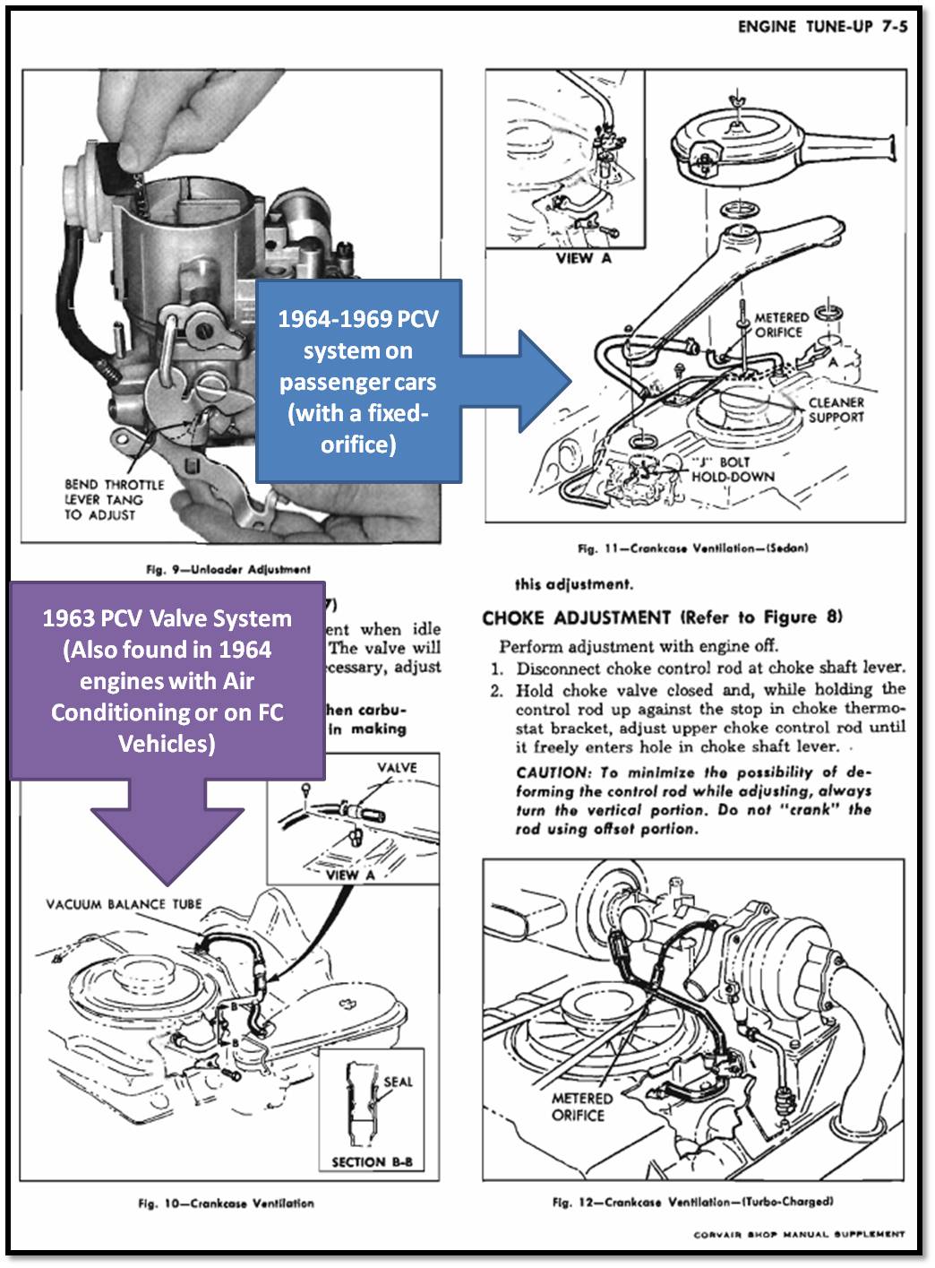
There appears to be a version that includes a breather filter on top. This would be similar to the type used as a direct breather filter attached to the crankcase breather tube, which could be used with the type of breather tube that includes a fixed orifice PCV system. However, this filtered breather could introduce crankcase fumes to the engine compartment, which could be then drawn into the engine fan to mix with the cooling air that could also introduce crankcase fumes into the passenger compartment via the Corvair heater/defroster system.
EVIL ENERGY Polish Baffled Universal Oil Catch Can Reservoir Tank Breather Filter Kit with 3/8" NBR Fuel Line Aluminum Blue

https://www.amazon.com/EVIL-ENERGY-Univ ... r=8-4&th=1
It might be desirable to remove the top-mounted breather filter, and then run another hose to the carburetor intake filter, so that any fumes would be drawn into the carburetor to be reburned and then exit out the tailpipe (as it does with a standard, unmodified PCV system).
EVIL ENERGY Polish Baffled Universal Oil Catch Can Reservoir Tank Breather Filter Kit with 3/8" NBR Fuel Line Aluminum Blue
It might be desirable to remove the top-mounted breather filter, and then run another hose to the carburetor intake filter, so that any fumes would be drawn into the carburetor to be reburned and then exit out the tailpipe (as it does with a standard, unmodified PCV system).
Brad Bodie
Lake Chatuge, North Carolina
1966 Corvair Corsa Convertible
Lake Chatuge, North Carolina
1966 Corvair Corsa Convertible-
Holyroller
- Posts: 69
- Joined: Sun Nov 01, 2020 7:56 am
- Location: Hesperia
Re: 1960 Monza Coupe
Wish I could have made it to Wrightwood car looks great
I get my 60 back from paint next week . 2 years in paint
I get my 60 back from paint next week . 2 years in paint
- Attachments
-
-
60 700 coupe
61 Lakewood
66 Monza
61 Lakewood
66 Monza
Re: 1960 Monza Coupe
To answer Brad...
65 110 engine, '64 3.55 posi diff, '64 4 speed trans.
pertronix system was on the car when I bought it.
Roger Parent throttle linkage? How do you like it?
yes and I love it.
Fuel pump isn't one I would have chosen and the location is wrong. That is all previous owner stuff I haven't had time to correct yet.
Scott
1960 Monza Coupe
1965 Evening Orchid Corsa Turbo (project)
1961 Rampside (project)
1964 Spyder coupe (patina car, running)
1964 faux Spyder (project/parts car)
1964 Monza (parts car)
1963 Monza (parts car)
1960 Monza Coupe
1965 Evening Orchid Corsa Turbo (project)
1961 Rampside (project)
1964 Spyder coupe (patina car, running)
1964 faux Spyder (project/parts car)
1964 Monza (parts car)
1963 Monza (parts car)
Re: 1960 Monza Coupe
bbodie52 wrote: ↑Sun Aug 22, 2021 4:11 pm There appears to be a version that includes a breather filter on top. This would be similar to the type used as a direct breather filter attached to the crankcase breather tube, which could be used with the type of breather tube that includes a fixed orifice PCV system. However, this filtered breather could introduce crankcase fumes to the engine compartment, which could be then drawn into the engine fan to mix with the cooling air that could also introduce crankcase fumes into the passenger compartment via the Corvair heater/defroster system.
It might be desirable to remove the top-mounted breather filter, and then run another hose to the carburetor intake filter, so that any fumes would be drawn into the carburetor to be reburned and then exit out the tailpipe (as it does with a standard, unmodified PCV system).
I am not running the breather. If you look closely you'll see there is a big shiny bolt in the top. That is how it comes. The breather is an optional ad on.
I run the crankcase to the inlet side and the outlet side is run to the balance tube. I couldn't run the crankcase breather into the air filters because I am not running the stock filters.
Scott
1960 Monza Coupe
1965 Evening Orchid Corsa Turbo (project)
1961 Rampside (project)
1964 Spyder coupe (patina car, running)
1964 faux Spyder (project/parts car)
1964 Monza (parts car)
1963 Monza (parts car)
1960 Monza Coupe
1965 Evening Orchid Corsa Turbo (project)
1961 Rampside (project)
1964 Spyder coupe (patina car, running)
1964 faux Spyder (project/parts car)
1964 Monza (parts car)
1963 Monza (parts car)
-
bbodie52
- Corvair of the Month
- Posts: 12143
- Joined: Mon Aug 06, 2012 12:33 pm
- Location: Lake Chatuge Hayesville, NC
- Contact:
Re: 1960 Monza Coupe
But the factory GM design utilizes a fixed "metered orifice" to provide some measure of control between the crankcase and the main vacuum balance tube. When vacuum levels are low (open throttle conditions) some degree of compensation for the low vacuum is an alternative of filtered air and draw into the carburetor intake. With your setup, it is tied ONLY to the vacuum source which is at its maximum vacuum during closed or partial throttle. When vacuum is low, would this closed system allow crankcase pressure to rise too much? A filter on either the OIL CATCH CAN or via a link tube to a carburetor air filter would give full throttle/high RPM/low intake manifold vacuum conditions a path for crankcase pressures under these conditions to vent via the air filter path alternate similar to the original PCV system. At high engine RPM speeds, crankcase pressure buildup is likely to be at its highest when the vacuum manifold extraction is at its lowest level. The other designed PCV path into the carburetor inlet air filter would seem to be necessary to avoid high crankcase pressure and contamination levels.
As mentioned before, without a metered orifice, would the "controlled vacuum leak" via an unrestricted path from the crankcase into the vacuum balance tube permit too much air to move into the balance tube? How much restriction comes from the OIL CATCH CAN device? Instead of a direct crankcase breather line into the OIL CATCH CAN, should the GM fixed orifice be included in that path to the OIL CATCH CAN device, and should a filtered breather be included also to duplicate the design of the original PCV system?
As mentioned before, without a metered orifice, would the "controlled vacuum leak" via an unrestricted path from the crankcase into the vacuum balance tube permit too much air to move into the balance tube? How much restriction comes from the OIL CATCH CAN device? Instead of a direct crankcase breather line into the OIL CATCH CAN, should the GM fixed orifice be included in that path to the OIL CATCH CAN device, and should a filtered breather be included also to duplicate the design of the original PCV system?
Brad Bodie
Lake Chatuge, North Carolina
1966 Corvair Corsa Convertible
Lake Chatuge, North Carolina
1966 Corvair Corsa ConvertibleRe: 1960 Monza Coupe
Yes that is probably some things I need to ad to it.bbodie52 wrote: ↑Thu Aug 26, 2021 11:23 am But the factory GM design utilizes a fixed "metered orifice" to provide some measure of control between the crankcase and the main vacuum balance tube. When vacuum levels are low (open throttle conditions) some degree of compensation for the low vacuum is an alternative of filtered air and draw into the carburetor intake. With your setup, it is tied ONLY to the vacuum source which is at its maximum vacuum during closed or partial throttle. When vacuum is low, would this closed system allow crankcase pressure to rise too much? A filter on either the OIL CATCH CAN or via a link tube to a carburetor air filter would give full throttle/high RPM/low intake manifold vacuum conditions a path for crankcase pressures under these conditions to vent via the air filter path alternate similar to the original PCV system. At high engine RPM speeds, crankcase pressure buildup is likely to be at its highest when the vacuum manifold extraction is at its lowest level. The other designed PCV path into the carburetor inlet air filter would seem to be necessary to avoid high crankcase pressure and contamination levels.
As mentioned before, without a metered orifice, would the "controlled vacuum leak" via an unrestricted path from the crankcase into the vacuum balance tube permit too much air to move into the balance tube? How much restriction comes from the OIL CATCH CAN device? Instead of a direct crankcase breather line into the OIL CATCH CAN, should the GM fixed orifice be included in that path to the OIL CATCH CAN device, and should a filtered breather be included also to duplicate the design of the original PCV system?

Scott
1960 Monza Coupe
1965 Evening Orchid Corsa Turbo (project)
1961 Rampside (project)
1964 Spyder coupe (patina car, running)
1964 faux Spyder (project/parts car)
1964 Monza (parts car)
1963 Monza (parts car)
1960 Monza Coupe
1965 Evening Orchid Corsa Turbo (project)
1961 Rampside (project)
1964 Spyder coupe (patina car, running)
1964 faux Spyder (project/parts car)
1964 Monza (parts car)
1963 Monza (parts car)