Coil and Resistance wire question

All Models and Years
User avatar
Gasman63
Posts: 207
Joined: Sun Feb 12, 2023 5:54 pm

Coil and Resistance wire question

Post by Gasman63 »

Sorry if I'm beating a dead horse here.
The wiring on my 63 Vert is a mess. Too many people in the past screwing with it. Cutting this and bypassing that. I will be replacing the Harnesses from bumper to bumper this coming winter but for now I just want to understand what has been done.
At the moment I have the heads off as I lost a Valve Seat and it destroyed a piston and head. So in the next month or so I hope to get it back together. BTW, the Gen. was replaced by an Alt. but I don't think that has much to do with my question.

Reading the schematics I see Main Batt. Voltage goes to the starter. From the starter via a Yellow wire it works its way to the Positive side of the coil. But NOT through the resistance wire. The Resistance wire is connected to the yellow wire but takes the resisted voltage after going through the wire to other parts of the car. Including indicator lights and to the ignition switch. I see the Violet wire that is coming off of the ignition switch is going to the starter also, so this could be lower voltage to trigger the starter. I'm not exactly sure on that.

My issue is... what I'm seeing is only the resistance of the Coil itself is dropping the voltage to the Points and Not the resistance wire. And the two do not combine to drop voltage with a resistance of 3 ohms. So you see, somewhere I'm not understanding or my schematics or wrong. I'm betting it me. :dontknow:

Please correct me. BTW, The resistance wire in my car is bypassed completely. And someone has put in a 3 ohm coil so I know my voltage to the points is lower.
1963 Corvair Monza Convertible 140 4 speed.
Colorado Springs :wave:
User avatar
toms73novass
Posts: 214
Joined: Sat Mar 04, 2017 6:58 am
Location: Grand Island NY

Re: Coil and Resistance wire question

Post by toms73novass »

Both the resistance wire and the yellow wire should be connected to the positive side of the coil.

The yellow wire only is energized when the starter is cranking. When the key is released the power goes through the resistance wire, the connection at the starter is broken when the solenoid is not energized.

In 64 they got sneaky with the resistance wire, they looped it near where it connects at the firewall and connected it to the yellow wire out of the starter loom so you don't see it near the coil.
1962 700 Wagon
1963 Spyder convertable
1965 Monza
1967 UltraVan 211
User avatar
Gasman63
Posts: 207
Joined: Sun Feb 12, 2023 5:54 pm

Re: Coil and Resistance wire question

Post by Gasman63 »

I'm looking at 63 schematics from this site.
I'm seeing the yellow wire is connected to the Resistance wire at a connector. If the yellow wire is only powered during starting then I think what I was misunderstanding is the power supplied to the resistance wire is actually coming from the ignition and not going to the ignition. This way when not in the starting mode power comes from ignition to resistance wire then to the coil.

Please correct me if I'm wrong but this is starting to make more since if this is right. :think:

My Resistance wire is connected to the 8 wire connector at both ends and not physically going to the coil. This must be the sneaky part you mentioned. :tu:

So which wire is feeding voltage to the ignition switch? Would that be the Violet wire?
1963 Corvair Monza Convertible 140 4 speed.
Colorado Springs :wave:
User avatar
toms73novass
Posts: 214
Joined: Sat Mar 04, 2017 6:58 am
Location: Grand Island NY

Re: Coil and Resistance wire question

Post by toms73novass »

Ahh I was looking at 62-63 manual and must have looked at 62, 63 has the "hidden" resistor wire like 64.

The blue line is the resistance loop connected to the yellow wire where it meets the starter yellow in the connector.

The orange in my scribble is the path to the ignition and red wire is the path from the ignition.

The orange path consists of a black wire from the voltage regulator to the multipoint junction in the harness that exits as red wires.
Attachments
1963 Corvair Passenger Car Combined Schematic.jpg
1962 700 Wagon
1963 Spyder convertable
1965 Monza
1967 UltraVan 211
66vairguy
Posts: 4717
Joined: Tue Dec 21, 2010 3:44 pm

Re: Coil and Resistance wire question

Post by 66vairguy »

toms73novass wrote: Wed May 01, 2024 6:24 am Both the resistance wire and the yellow wire should be connected to the positive side of the coil.

The yellow wire only is energized when the starter is cranking. When the key is released the power goes through the resistance wire, the connection at the starter is broken when the solenoid is not energized.

In 64 they got sneaky with the resistance wire, they looped it near where it connects at the firewall and connected it to the yellow wire out of the starter loom so you don't see it near the coil.
Tom summed it up well, BUT the 62-63 shop manual shows the resistance wire looped in the harness and to the starter wires connector. Fact is Chevy moved the resistance wire from the coil to the starter plug and back to the coil (in 1969). The EM Corvair schematics, especially 1960-61 are not the best. Also note the 62-63 Spyder (turbo) cars used no resistance wire, but a ceramic resistor mounted on the rear body rail near the coil.

Bottom line is to understand how this works. The ignition key supplies power to the resistance wire (or ceramic resistor) and it goes to the coil "+" terminal OR the small plug that connects to the starter. The starter ALSO supplies power to the coil "+" terminal ONLY when it is running (engaged). WHY? Both paths supply power so they are parallel and in electricity the path of least resistance supplies more electrical energy. When the starter is off the coil "+" terminal only gets power from the resistive wire (either it goes to the coil, or it goes to the starter plug and connects to the "YELLOW" wire to the coil that is low resistance. Either way works the same. When you start the car the battery voltage drops (a lot in cold weather) so a switch in the starter connect the main battery cable (to the starter) voltage to the coil "+" terminal to negate the voltage drop in the resistance wire, or more voltage to coil for a hotter spark during starting. A very elegant solution to allow a lower voltage to the coil during running, but higher during starting. Most GM cars used this scheme for decades!!!

Yes the coil has resistance. The wire is about 1.8 ohms, the coil is about 1.3 ohms (total about 3.1 ohms). So yes you get a voltage drop at the wire, AND across the coil. Ideally based on math ----
POINTS CLOSED = input to wire = 14VDC, input to coil "+" = 6VDC, output at coil "-" = 0VDC.
POINTS OPEN = input to wire = 14VDC, input to coil "+" = 14VDC, output at coil "-" = 14VDC.

Of course there are tolerances and the resistance from the coil "-" through the wire and the points is not absolute zero to ground. In a good system variations are minor.

Why is the power switched from about 14VDC to 6VDC and back? That is how a transformer (coil) works - transforms a low voltage to a high voltage (depending on how it is built) as the voltage is switched -- this is why homes use AC as alternating voltages and currents are needed to make the line transformers work.
User avatar
bbodie52
Corvair of the Month
Posts: 11949
Joined: Mon Aug 06, 2012 12:33 pm
Location: Lake Chatuge Hayesville, NC
Contact:

Re: Coil and Resistance wire question

Post by bbodie52 »

The original Delco coil primary resistance value of 1.28-1.42 ohms was likely chosen to match with the 1.8 ohm ballast resistor wire value to produce about 3 ohms of total resistance for the Delco coil Primary to manage heat buildup within the coil. At the same time, the voltage divider circuit was designed to reduce arcing and burning of the points contacts by minimizing the voltage as much as possible during normal engine operation, but this made the coil secondary output too weak to get the cold engine started reliably during engine cranking, so the starter solenoid was used to momentarily compromise the voltage divider resistor circuitry to promote engine starting.

The GM design engineers integrated all of these features into the ignition circuitry to optimize the system for initial startup, and for continued running, and to get the longest life with acceptable reliability out of the system. In other words, they looked at the whole system and designed it using available technology and components to cover the changing environment during engine startup and operation.

1963 Corvair Engine Compartment Wiring (Ignition Circuit).jpg
When the ignition switch is turned to the ON position, voltage is routed back to the engine compartment to power the ignition coil. This voltage is normally routed through a ballast resistor wire to reduce the 12 VDC provided by the battery and charging system to only about 7 VDC. This lower voltage reduced the electrical current flowing through the ignition coil and ultimately through the ignition points to GROUND. The points are simply an ON/OFF switch that turns the current through the ignition coil PRIMARY winding on and off as the points are actuated by the cam inside the distributor. WHEN THE POINTS CLOSE, CURRENT FLOWS THROUGH THE COIL PRIMARY WINDING. WHEN THE POINTS OPEN THEMAGNETIC FIELD IN THE COIL PRIMARY COLLAPSES, WICH INDUCES A HIGH VOLTAGE THROUGH THE SECONDARY WINDING TO SEND A SPARK VOLTAGE TO A SPARK PLUG. (The rotor and cap determine which spark plug gets the high voltage).

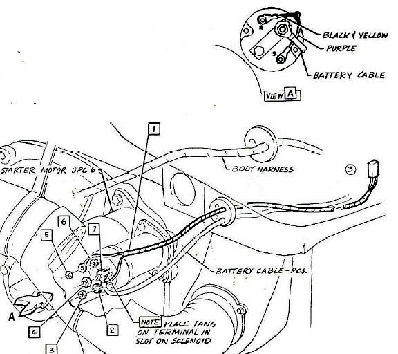
Ig you watch the starter activity in the diagram below, you will see the solenoid physically moves the starter drive gear to engage it with th large ring gear on the clutch or torque convertor, to rotate the engine for starting. AT THE SAME TIME THE DRIVE GER ENGAGES THE ENGNE RING GEAR, A LARGE DISC ON THE LEFT END OF THE SOLENOID CONNECTS THE THICK BATTERY CABLE TO THE STARTER MOTOR, TO ACTIVATE THE MOTOR TO TURN THE ENGINE.

That same disc that feeds a large amount of current to the motor simultaneously connects with another terminal connection on the back of the solenoid. This routes electricity to the electrical connector that is spliced to the resistor wire that normally feeds the coil and points. WHILE THE RESISTOR WIRE NORMALLY REDUCES THE IGNITION SWITCH VOLTAGE FROM 12.5 VDC TO ABOUT 7 VDC, THE 12.5 VDC THAT IS ADDED AT THE SPLICE CONNECTION FROM THE SOLENOID SUPERCEDES THE 7 VDC, AND THE HIGHER VOLTAGE TEMPORARILY TAKES OVER — FEEDING THE HIGHER BATTERY VOLTAGE DIRECTLY TO THE COIL POSITIVE TERMINAL. (The 7 VDC from the ignition switch/resistor wire is still there, but since 12.5 VDC is electrically spliced in to the same wire, the voltage from the starter solenoid connection supersedes the lower resistor wire voltage. This results in a "hotter" spark plug voltage from the coil, but only as long as the starter is cranking the engine. The "hotter" spark from the coil helps the cold, slowly cranking engine to get started. At the moment the engine starts, the driver releases the key, which disengages the purple wire voltage to the solenoid. which allows the solenoid to relax and simultaneously stop the starter motor while the drive gear disengages from the ring gear. This action also stops the added voltage from connecting to the ignition coil, so the coil only gets what is left — 7 VDC coming from the ballast resistor wire. The spark plug voltage coming form the coil is then reduced, but is still deemed to be high enough to keep the engine running.

Image

The 3.0 ohm aftermarket coil is designed to be powered by a full 125 VDC battery voltage all the time. Its internal 3 ohm Primary produces a good spark plug voltage, and the coil will not overheat because of the internal current-limiting resistance of the 3 ohm primary winding. This also limits the amount of current running through the points, to protect the points. IF THE BALLAST RESISTOR WIRE HAD BEEN LEFT IN THE CIRCUIT, THE TOTAL CIRCUIT RESISTANCE WOULD BE TOO MUCH, AND WOLD SERIOUSLY WEAKEN THE COIL OUTOUT TO THE SPARK PLUGS. For this reason, the external ballast resistor must be bypassed to properly power the aftermarket ignition coil. The new ignition coil gets 12.5 VDC all the time — whenever the key is in the ON position. The extra yellow wire coming form the solenoid would no longer have any affect on the ignition circuit.

Image

The circuitry that GM used for decades was designed ONLY to prolong the life of the ignition points contacts. The use of a mechanical switch (POINTS) was the only method they had during those years to switch the coil on and off at such a rapid pace. The engineers also determined that a stronger spark plug voltage was needed to get the cold engine running, so they came up with the external ballast resistor (integrated wire or ceramic resistor) to permit the starter solenoid to determine the amount of voltage feeding the coil while cranking the engine, or with the engine running. The newer design of the aftermarket 3.0 ohm coil still protects the points by limiting the current flowing across the points contacts. At the same time, the coil internal redesign produces a strong spark to start the car, and continues with the same spark output for normal engine operation. WITH THE 3.0 OHM COIL IN OPERATION, THE EXTERNAL BALLAST RESISTOR WIRE MUST BE PERMANENTLY BYPASSED FOR THE COIL TO BE POWERED PROPERLY.
Brad Bodie
Lake Chatuge, North Carolina
Image 1966 Corvair Corsa Convertible
66vairguy
Posts: 4717
Joined: Tue Dec 21, 2010 3:44 pm

Re: Coil and Resistance wire question

Post by 66vairguy »

As I like to remind Brad --- the 3.0 ohm coil results in inferior coil output voltages and spark at the spark plug during starting. It's a lazy way to avoid using a ballast resistor. Adequate for warm weather use.

The DELCO engineers knew what they were doing.
66vairguy
Posts: 4717
Joined: Tue Dec 21, 2010 3:44 pm

Re: Coil and Resistance wire question

Post by 66vairguy »

gasman63 --- I recall you car is a mix of parts and I think it had the Spyder instrument cluster. The 62-63 shop manual does a poor job of showing the different wiring for the Spyder. I mentioned the 62-63 used a different ceramic ballast and coil. Here is an article from SCC about it. You have can use the Spyder harness and a 1.8ohm ballast with standard 1.3 ohm coil, or use the standard harness with ballast wire and standard coil and add the wires for the temperature gauge and tachometer.
Attachments
20211117 The special 62-63 Spyder ballast and coil-2.pdf
(84.38 KiB) Downloaded 7 times
User avatar
bbodie52
Corvair of the Month
Posts: 11949
Joined: Mon Aug 06, 2012 12:33 pm
Location: Lake Chatuge Hayesville, NC
Contact:

Re: Coil and Resistance wire question

Post by bbodie52 »

66vairguy wrote: » Wed May 01, 2024 1:59 pm

As I like to remind Brad --- the 3.0 ohm coil results in inferior coil output voltages and spark at the spark plug during starting. It's a lazy way to avoid using a ballast resistor. Adequate for warm weather use.

The DELCO engineers knew what they were doing.

Image
Image
The internal design and structure of an ignition coil manufactured with 3.0 ohm Primary winding instead of a 1.5 ohm coil Primary can certainly be adjusted to take into account its usage with a 4 or 6 cylinder engine that runs at non-racing RPM ranges, and with fewer ignition impulses per crankshaft revolution to permit a full spark plug output voltage,

Ignition coil performance is dependent on the Turns Ratio, Inductance and Coil Resistance, provided the ‘dwell’ is sufficient for a full recharge between firings. In a conventional Ignition system, the dwell is fixed and the engine will start to misfire if the RPM goes beyond the ‘dwell’ limit, resulting in loss of power. This causes ignition system crashes and the engine may coast till the coil recharges resulting in loss of power and speed. Ignition systems which uses electronics to predict and adjust the dwell helps solve this to a certain extent. But all conventional Inductive Ignition systems are susceptible to spark roll off at higher rpm despite the electronic ignition systems.

PERTRONIX RATES BOTH THEIR 1.5 OHM AND 3.0 OHM COILS WITH A SECONDARY OUTPUT OF 40,000 VOLTS. Since the internal Primary coil resistance has changed, but the output voltage remains the same, it is logical to assume that Pertronix engineers have adjusted the turns ratio and inductance of the internal coils to adjust for the increased Primary resistance, so that the output to the spark plugs will remain the same. This can also be true with other aftermarket coils produced b different manufacturers as well. Dropping the external ballast resistor and providing the coil with full electrical system voltage of 12.5 -14.5 VDC permits all of these design factors to be adjusted to protect the ignition points while providing the engine with appropriate secondary output voltage from the 3.0 ohm coil.


Image 3 ohm coilsImage
Last edited by bbodie52 on Wed May 01, 2024 5:33 pm, edited 1 time in total.
Brad Bodie
Lake Chatuge, North Carolina
Image 1966 Corvair Corsa Convertible
User avatar
Gasman63
Posts: 207
Joined: Sun Feb 12, 2023 5:54 pm

Re: Coil and Resistance wire question

Post by Gasman63 »

Starting from the top...

Thanks Tom for helping me understand what the schematics were actually saying. Sometimes I get messed up on direction. And your colored diagram helped.

Bob, Your saying its a weak way about it because of the less voltage (more resistance than factory) being given to the points while starting? If so then a simple adding of the ceramic ballast resistor would bring it back up to where it should be. So thanks for explaining that.

Bob, Please confirm this was the point you were making on the summer time running and weak ability.

BTW, You are right as far as my 63 Vert. goes. Its a Mutt. A mix of a few things. With the help of Steve I've figured out the block is 110 and the rear engine mount is a 64. The heads are 65 - 66 140. 4 carbs also helped figure this out. LOL. The cam and dist. are for 140. and I have separate dual exhaust. Plus as you stated I have the Spyder dash including the Thermistor for the temp gauge. So Steve recommended replacing the Wiring harnesses (when the time comes) with 64 Spyder harnesses. No matter how many different Corvairs it was put together with it still looks good :tu:

Brad, Thanks for explaining why the resistor wire was by-passed. Its makes sense with the fact the coil is now 3.0 ohm. I know some other crazy safety thing was done with a pressure switch that I don't want to get into but I'm sure that my power to the coil has to be coming from the ignition and possible where the resistance wire connection was disconnected. This would give the full voltage to the coil and be switched.

I will have to take out some crazy ideas and fix some ugly wiring but with this info I have received today I feel better about what I'm looking at.
IMG_20240501_182010703_HDR.jpg
Sorry the picture is sideways.
1963 Corvair Monza Convertible 140 4 speed.
Colorado Springs :wave:
joelsplace
Posts: 2045
Joined: Wed Oct 13, 2010 12:51 pm
Location: Northlake, TX

Re: Coil and Resistance wire question

Post by joelsplace »

Let's pretend the claimed output is real. A 3 ohm coil loses the voltage help when the starter is engaged so how could it be just as good? If it was GM would have saved the expense of the resistance wire and the wire coming from the starter and the extra contact in the solenoid.
157 Corvairs, 5 Ultravans and counting
Northlake, TX
User avatar
bbodie52
Corvair of the Month
Posts: 11949
Joined: Mon Aug 06, 2012 12:33 pm
Location: Lake Chatuge Hayesville, NC
Contact:

Re: Coil and Resistance wire question

Post by bbodie52 »

The Pertronix 3.0 ohm ignition coil has been relocated from the original Corvair coil mounting location next to the distributor. This is generally a good move as it takes the coil away from mounting on the hot cylinder head to reduce heat transfer from the hot cylinder head to the coil body. HOWEVER... Most ignition coils are oil-filled and it is preferred to mount them vertically, with the wire connections on top. A vertical orientation assures that all of the internal coil windings are bathed in liquid oil, to help cool the coil wires. Mounting the coil on its side may uncover a portion of the coil windings on the inside top. Recommend you remount the coil with vertical orientation.

Image
T1203YN


T1203YN
Image
T = Tonawanda, New York (GM Tonawanda Engine Plant)
http://media.gm.com/media/us/en/gm/comp ... wanda.html
1203 = Engine manufacturing date (month and date). December 3rd. (If it is the original engine, probably 12/03/1963)
"YN" is from 1961-1964 (No year is included in the date stamp, unfortunately).
YN
1961: 98hp — 145 CID (Cubic Inch Displacement), 9:1 Compression Ratio, with Manual Transmission — Corvair 500, 700 and 900 Monza only.
1962-1963: 102hp — 145 CID (Cubic Inch Displacement), 9:1 Compression Ratio, with Manual Transmission — Corvair 500, 700 and 900 Monza only.
1964: 110hp — 164 CID (Cubic Inch Displacement), 9:1 Compression Ratio, with Manual Transmission — Corvair 500, 700 and 900 Monza only.


Corvair Ignition Coil Mount (2).jpg

Image

The table below is from the Clark's Corvair Parts online catalog, and it indicates that the suffix code ZH was, in fact, used on 1964 95hp164 CID Powerglide transmission engines! If your engine has a magnesium cooling fan, or a Positive Crankcase Ventilation (PCV) system using a fixed orifice and no road draft tube or PCV valve, it might be a 1964 engine! The distributor number (on the distributor housing facing the engine shroud) and the cylinder head casting number will help to confirm the engine type.

Engine Identification Numbers (LEFT-CLICK IMAGE TO ENLARGE) Click twice for maximum enlargement


Image


Image
1960-61 distributor on the right. Electronic breakerless ignition systems will only fit 1962-69 distributors.


Image


Image


5607 signifies it from an early 145 CI engine.
7293 signifies it from an early 145 CI turbo engine.
8409 signifies it's from the late 164 CI engines, regardless of HP.


Image


Image
1964 and Later PCV Tube wit Fixed Orifice

Image
1963 Engine with PCV System Using a PCV Valve

Image
1962 and earlier Corvair with Road Draft Tube and Oil Pressure Warning Switch down below...
Brad Bodie
Lake Chatuge, North Carolina
Image 1966 Corvair Corsa Convertible
User avatar
Gasman63
Posts: 207
Joined: Sun Feb 12, 2023 5:54 pm

Re: Coil and Resistance wire question

Post by Gasman63 »

Joel, I agree with your train of thought. I cant argue that point as I'm far from an electrical engineer.

OK Brad. Just for you, plus its my Saturday night and I'm sitting here having a cold one.

The Fan was replaced. I have no clue if the style had been changed or was the same. Dad said the bearing went out on a club trip and someone had just the part he needed. Maybe the bearing only was changed? I dont know. And Dads mind is just not that sharp anymore.

Remounting the coil is easy. Well as long as the coil wire reaches. Thanks for pointing that out.

Being the cars date is Dec 1963 I've leaned toward 1964. Dad says and the registartion says 1963. But Steve says it has a 1964 mount so??? Again, I'm leaning towards a 1964 110HP

Fixed oriface and no PCV and no Road draft tube. 1964

Distributor Number 1110330. 1965 or 1966

Head number 3878570. 1965 or 1966 140

Cam Number 383 9891. 110/140

Crank number 8409. 164CID

Balancer is 1964 to 1969 but I have no clue if it has ever been changed.

So, I'm going with 1964 engine in a 1963 convertible. BTW, I cant even go by the emblems on the car as Dad changed them all out for Spyder Emblems and changed Dash and Glove Box for Spyder ones. Evan though its not a Spyder. He had a 1963 Spyder when he was a younger man.

Now, What do you say it is Brad?
Reminds me of that Cadillac Song by Johnny Cash. :) As far as I know Dad found the car, reworked it including the body work and top and dropped a 1964 engine in it and seats from a Nissan. He used to restore 1959 impala convertibles for fun after retiring so he knows old Chevy's. Then maybe he wanted more power so he had 140 heads put on it. At least that's what it feels like to me.
1963 Corvair Monza Convertible 140 4 speed.
Colorado Springs :wave:
User avatar
Frank DuVal
Posts: 491
Joined: Wed Dec 09, 2009 4:58 pm

Re: Coil and Resistance wire question

Post by Frank DuVal »

Stock location for ignition coil on AC Corvairs is horizontal on the rear body panel, just like Gasman has his mounted. Same with '56 Buicks. They work a long time, like almost forever.

Just saying, it works, don't trust stuff you hear on the internet! OMG, the coil will fail if mounted anyway but vertical with the terminals up. That little nugget has been floating around and repeated for 20 years.
:rolling: :rolling: :rolling: :rolling: :rolling:
Frank DuVal

Fredericksburg, VA

Hey look, blue background! :wink: :thumbsup: :car: :spider: :frog: :train:
User avatar
bbodie52
Corvair of the Month
Posts: 11949
Joined: Mon Aug 06, 2012 12:33 pm
Location: Lake Chatuge Hayesville, NC
Contact:

Re: Coil and Resistance wire question

Post by bbodie52 »

:google: :search: :link: https://www.google.com/search?q=ignitio ... nt=gws-wiz

:dontknow: Click on the above link for many opinions on coil mounting orientation. There are many opinions, just like you will see on the Corvair Forum! Some of us will recommend following manufacturer's instructions, and others will recommend ignoring the aftermarket equipment instructions.

Image

:rolling:
Brad Bodie
Lake Chatuge, North Carolina
Image 1966 Corvair Corsa Convertible
66vairguy
Posts: 4717
Joined: Tue Dec 21, 2010 3:44 pm

Re: Coil and Resistance wire question

Post by 66vairguy »

Frank DuVal wrote: Wed May 01, 2024 7:45 pm Stock location for ignition coil on AC Corvairs is horizontal on the rear body panel, just like Gasman has his mounted. Same with '56 Buicks. They work a long time, like almost forever.

Just saying, it works, don't trust stuff you hear on the internet! OMG, the coil will fail if mounted anyway but vertical with the terminals up. That little nugget has been floating around and repeated for 20 years.
:rolling: :rolling: :rolling: :rolling: :rolling:
Good comments Frank --- The reason the Corvair coil was mounted on the engine was for lower assembly costs. As many know the coil gets HOT from engine head heat. Since it was in the way of the A/C belt it HAD to be moved to the rear body brace and it runs cooler (and lasts longer). This required a longer coil to distributor wire and extra labor or MORE COST. Check what Chevy charged for A/C on a Corvair - stunning. They made money off that option.

YES the coil NOT vertical failure was mostly an exaggeration/myth, but some poor quality coils did leak oil past the seal below the center terminal, if not mounted vertically, which caused them to fail. I've NEVER seen a DELCO coil leak. Easy to check, pull out the high tension center wire and look to see if there is oil around the terminal.
Post Reply

Return to “Ask your Mechanical Questions here”