Melting wires, simple question

All Models and Years
cnicol
Posts: 595
Joined: Wed Jan 20, 2010 8:11 pm

Re: Melting wires, simple question

Post by cnicol »

NMVair wrote: Fri Apr 19, 2024 9:14 am I have a 64 service manual. Since I have a 68 140 in the car should I get a late model diagram?
The '64 manual is the closest you're going to get; the '68 manual won't provide any useful information.

Since your car has been converted to an internally regulated alternator, this diagram should be pretty close. Note there are likely variations because not all conversions "look" alike. Electrically, this diagram is proven
Corvair EM + 10Si Int. Reg. alt. schematic.jpg
and has been used by myself (I drew it) and dozens, if not hundreds of others.

The usual variation occurs in the tie-point between the diagram's blue, red, black, and battery pigtail. They all tie together but the location of that tie-point varies.
'61 140 PG Rampside
'66 Rear Alum V8 4-dr
'60 Monza PG coupe (sold, sniff, sniff)
'66 Corsa Fitch Sprint Conv. (First car 1971, recently repurchased)
66vairguy
Posts: 4690
Joined: Tue Dec 21, 2010 3:44 pm

Re: Melting wires, simple question

Post by 66vairguy »

Craig's diagram is good. Never assume the colored wires are going to the expected place.

I usually find EM conversions with many patches and kludged wiring. I usually cut it all out and simplify the number of wires and connections.

I solder and heat shrink any splices.
joelsplace
Posts: 2031
Joined: Wed Oct 13, 2010 12:51 pm
Location: Northlake, TX

Re: Melting wires, simple question

Post by joelsplace »

66vairguy wrote: Wed Apr 17, 2024 10:11 am That said the "3.0 ohm High Performance coil" is a myth.
What evidence do you have that 3 ohm coils don't have 3 ohms worth of windings and have a resistor instead?
I couldn't find any info one way or the other.
157 Corvairs, 5 Ultravans and counting
Northlake, TX
User avatar
sethracer
Posts: 30
Joined: Sun Dec 13, 2009 5:06 pm

Re: Melting wires, simple question

Post by sethracer »

"Almost" any coil will fire the plugs, when properly triggered. In my experience, and with a few users reminding me of electronics math, I changed my recommendation (many years ago, now) to the 3.0 Ohm coil. The higher the resistance rating - actually the total resistance of the coil energizing circuit - the less current will flow, at the same supply voltage. The distributor internal electronics has two functions. The distributor management circuit inside takes the input from the magnetic pulse of the pick-up based on position, uses that input data to tell the coil control circuit when to switch on and off the grounding side of the coil. (this fires the ignition) That management circuit would really rather have a 12V supply. It is usually connected to the coil power feed terminal, (although it really doesn't need to be) this makes sense, for ease of install, to have it connect there. That is why I recommend bypassing the resistance circuit in the harness, and giving full battery voltage to the dist. BUT, that means, with the common install, that you are supplying a full battery voltage to the coil. Great for (most) coils, but with a low resistance coil and no other resistance in the circuit, you are asking the switching circuit in the distributor to switch a lot more current. This would stress out the electronics and could cause failures. That is why I recommend the 3.0 Ohm coil with a full battery voltage supply. You still have plenty of spark, the distributor control circuit has a happy voltage, and the switching circuit inside the distributor is not overstressed. What's not to like?
Corvair Enthusiast.
User avatar
Frank DuVal
Posts: 445
Joined: Wed Dec 09, 2009 4:58 pm

Re: Melting wires, simple question

Post by Frank DuVal »

What evidence do you have that 3 ohm coils don't have 3 ohms worth of windings and have a resistor instead?


None, as some do and some don't. It is how the manufacturer made it inside. Back in the old days I saw many coils with "INTERNAL BALLAST" stamped on the case.

But, as long as it is approx. three ohms across the primary terminals, I don't care how the manufacturer did it internally.
:tu: :dogrun: :dogrun: :dogrun: :dogrun: :dogrun: :drinkinbuddy: :drinkinbuddy:
Frank DuVal

Fredericksburg, VA

Hey look, blue background! :wink: :thumbsup: :car: :spider: :frog: :train:
66vairguy
Posts: 4690
Joined: Tue Dec 21, 2010 3:44 pm

Re: Melting wires, simple question

Post by 66vairguy »

joelsplace wrote: Fri Apr 19, 2024 9:10 pm
What evidence do you have that 3 ohm coils don't have 3 ohms worth of windings and have a resistor instead?
I couldn't find any info one way or the other.
Some might have 3 ohms of internal windings, I've never found one without the internal ballast --- Why? Simple economics. Extra windings cost MORE then installing an internal ballast.

You can go online and find why ballasts were used with ignition coils. Especially when the U.S.A. went from 6 volt to 12 volt electrical systems. Oddly enough there were a few 6 volt system cars that used ballasts with ignition coils, but these were on engines with very low compression so a cheaper (less spark energy) ignition coil could be used to ----- save money.

While we may roll our eyes at manufacturing "penny pinching" --- the consumer almost always buys the most they can get for the lowest price. I used to buy a quality ignition coil, but now it is not made. I talked to the company representative and was told "We started making a less expensive version along with the older more expensive quality versions. After a few years there was no consumer demand for the more expensive quality version and we stopped making it".
User avatar
bbodie52
Corvair of the Month
Posts: 11937
Joined: Mon Aug 06, 2012 12:33 pm
Location: Lake Chatuge Hayesville, NC
Contact:

Re: Melting wires, simple question

Post by bbodie52 »

I have read many comments on this Forum and on other technical forums that continue to debate whether or not to bypass the original vehicle ballast resistor wire to provide full voltage to the Pertronix components. Some declare the Pertronix ignition coils to be "junk", and the Pertronix installation and troubleshooting instructions to be "trash". I would suggest that if you are going to trust the Pertronix hardware quality enough to actually purchase it for your Corvair, then you should also trust the installation instructions published by that company enough to follow the instructions to the letter — instead of selectively ignoring the bits and pieces that some in the debate disagree with. I would suggest following the instructions and guidelines provided by Pertronix and give them the "benefit of the doubt" (the state of accepting something/someone as honest or deserving of trust even though there are doubts), to see if their instructions actually clear up your operating problems.

It is harder for the voltage to jump the spark plug gap when the engine is under load and combustion chamber pressures increase. If you begin with a weak spark that is allowing the engine to idle, but performance worsens as you try to accelerate, your ignition system may be running poorly due to inadequate voltage from the vehicle. Use a multimeter to confirm the voltages and grounds. Alternately, if you don't have a multimeter but suspect the possibility of low source voltage from the vehicle to the coil, you could prove the theory by simply running a temporary bypass wire directly from the battery positive terminal to the coil positive terminal and then taking the car on a test drive! If the car runs well under this test scenario, you have in-effect confirmed the suspicions and can then move forward to make a permanent change by bypassing the resistor wire in the vehicle wiring harness.

Image


The 3.0-ohm coil should be used on PerTronix Ignitors installed on four- and six-cylinder engines while 1.5-ohm coils should be used for eight-cylinder applications.
ImageImage

Choosing The Correct Ignition Coil
Ron Ceridono - Writer - Jan 25, 2017


In simple terms coils are rated by their primary resistance—less resistance in the primary windings of the coil allows more current to flow, which makes a stronger magnetic field. When the points open (or the electronic device that controls current flow shuts off) the magnetic field collapses and makes a spark in the secondary windings. It stands to reason that more current in the primary is a good thing, however the current flow is limited by the ability of the points, or the electronics in place, to handle it. Too little resistance means too much current flow, which can burn up points and damage electronic components.

For specific recommendations we contacted our pal, Don Lindfors, at PerTronix to get the straight story on coils. As he explains, PerTronix offers three oil-filled, canister-style coils and they are identified by the ignition system they are suited for:

The Flame Thrower 40,000V coils have internal resistance rated at 1.5 or 3.0 ohms. The 3.0-ohm coil should be used on PerTronix Ignitors installed on four- and six-cylinder engines while 1.5-ohm coils should be used for eight-cylinder applications. These coils can be used on virtually any inductive (non-capacitive discharge) ignition system.

Flame Thrower II coils have lower resistance, 0.6 ohms for use with Ignitor II ignition systems as well as many other high-energy ignitions. The low resistance helps to produce up to 45,000 V. This higher voltage allows larger spark plug gaps for added power and better fuel economy.

Flame-Thrower III coils were developed for use with the new Ignitor III electronics. The extremely low resistance of 0.32 ohms results in 45,000 V and a coil that charges to peak, current typically 30-70 percent faster the other coils. It should be noted that these coils are compatible with Ignitor III electronics only.
:link: https://www.motortrend.com/how-to/choos ... tion-coil/

PerTronix 40011 Flame-Thrower Coil 40,000 Volt 1.5 ohm
PerTronix 40511 Flame-Thrower Coil 40,000 Volt 3.0 ohm
ADDITIONAL INFORMATION: While it's the perfect coil to go with the PerTronix Ignitor breakerless ignition, our 40,000 volt Flame-Thrower canister coil can benefit virtually any distributor type inductive system. Its higher voltage allows larger spark plug gaps for added power, smoother response and better fuel economy. These coils are internally resisted so installation and wiring is drastically simplified. Our oil filled coils offer great heat control for street driven vehicles, while our epoxy filled coils provide superior winding support for high vibration environments in off-road vehicles and boats.
A 12V points type coil needs a resistance of around 3 ohms to give good performance without overheating. The big advantage of electronic ignition is that it can provide the correct dwell time to suit the revs, thus not overheating the coil at low revs and still giving a good spark at high revs.

Ignition coil performance is dependent on the Turns Ratio, Inductance and Coil Resistance, provided the ‘dwell’ is sufficient for a full recharge between firings. In a conventional Ignition system, the dwell is fixed and the engine will start to misfire if the RPM goes beyond the ‘dwell’ limit, resulting in loss of power. This causes ignition system crashes and the engine may coast till the coil recharges resulting in loss of power and speed. Ignition systems which uses electronics to predict and adjust the dwell helps solve this to a certain extent. But all conventional Inductive Ignition systems are susceptible to spark roll off at higher rpm despite the electronic ignition systems.

PERTRONIX RATES BOTH THEIR 1.5 OHM AND 3.0 OHM COILS WITH A SECONDARY OUTPUT OF 40,000 VOLTS. Since the internal Primary coil resistance has changed, but the output voltage remains the same, it is logical to assume that Pertronix engineers have adjusted the turns ratio and inductance of the internal coils to adjust for the increased Primary resistance, so that the output to the spark plugs will remain the same.

The difference in TURNS RATIIO when comparing the 1.5 ohm and 3.0 ohm 40,000 volt coils is reflected in the charts below. The recommended 3.0 ohm coil for a four or six-cylinder engine compensates for the fewer number of cylinder firings per engine rotation. The resulting difference in primary coil "charge time" could produce more heat buildup in the Primary coil at any given engine RPM. The higher internal Primary resistance in the 3.0 ohm coil reduces current flow and associated heat buildup based on a 12 VDC input constant. A different turns ratio in the 3.0 ohm coil helps to return the secondary output back to 40,000 volts, so the changes in input resistance and turns ratio of the 3.0 ohm, 40,000 volt coil makes it optimum for a six-cylinder engine.


Image

ImageImage
Last edited by bbodie52 on Sun Apr 21, 2024 9:00 am, edited 4 times in total.
Brad Bodie
Lake Chatuge, North Carolina
Image 1966 Corvair Corsa Convertible
NMVair
Posts: 462
Joined: Mon Jun 08, 2015 5:52 pm

Re: Melting wires, simple question

Post by NMVair »

Qualified and done right!!
Attachments
20240420_154417.jpg
20240420_154414.jpg
20240420_154411.jpg
NMVair
Posts: 462
Joined: Mon Jun 08, 2015 5:52 pm

Re: Melting wires, simple question

Post by NMVair »

Afyer the fix. The ",Gen Fan" light has come on. Which may have been the reason I got melted wires I.the first place. What I did was turn the plug upside down on the alternator, switching numbers 1 and two posts.
Other than that the car runs great. The old harness was as decrepit as they come.
66vairguy
Posts: 4690
Joined: Tue Dec 21, 2010 3:44 pm

Re: Melting wires, simple question

Post by 66vairguy »

I guess Brad's rant was aimed at me since I'm the one who has stated the Pertronix instructions are vague and sometimes misunderstood. I'm now sure why he as such trust in Pertronix when the facts contradict what he is saying about "trusting them". Maybe he works for them.

Fact -- Nothing wrong with Pertronix Ignitor if installed correctly and I've fixed a number of incorrect installations. I can't believe all the folks that had installation issues were stupid. After talking to them it is clear the Petronix installation instructions were not specific enough.

Fact --- The Petronix Ignitor II has a misfire problem on the Corvair at idle, especially noticeable on the Powerglide transmission cars in drive because of the lower idle than on a manual transmission car. Petronix has known about this for years and yet still sells them for use on six cylinder cars!

Fact --- The Pertronix coil catalog says to use a 3.0 coil for ALL six cylinder cars. This is just silly as different six cylinder cars use different coils. The Corvair coil primary is about 1.3 ohms and the ballast is about 1.8 ohms.

Pertronix quality control issues with their coils has been stated by more than one source. Some batches work great, other batches fail quickly per many posts online. Why pay more for intermittent quality when a good quality (and less expensive) coil does the job.

Fact ---- Bob Helt and others busted the "Hi-output" aftermarket coil myth when they tested them (including the Flamethrower) against a stock Corvair 140HP engine coil and NONE of the aftermarket coils performed better.

That said everyone can make their own choice. For me, as Ronald R. used to say "Trust, but verify".
NMVair
Posts: 462
Joined: Mon Jun 08, 2015 5:52 pm

Re: Melting wires, simple question

Post by NMVair »

I'm glad your having a great conversation about coils. Interesting. But my alternator is only charging at between 12 and 12.5 volts
And the fan light is on. It must have been doing this all the while since the light has been on since I got a higher output alternator rebuilt for the car.
It should be charging at a higher voltage rate, correct?
But tye car starts and runs great.
I know because I checked it twice- IT IS WIRED AS I WAS TOLD! My question is will this slight lack of voltage cause the light to come on so bright???
Ok back to your coil conversation.
:assault:
User avatar
Frank DuVal
Posts: 445
Joined: Wed Dec 09, 2009 4:58 pm

Re: Melting wires, simple question

Post by Frank DuVal »

For the coil conversation:

I agree with 66vairguy on all points.

BTW, the coil voltage only rises as high as the spark plug (and rotor gap) lets it. AS soon as the spark plug fires (just like the rotor gap fires) the gap becomes zero ohms, so the voltage goes to zero. You just need to have enough voltage to fire these two gaps. 45 KV coil? Just how wide are your gaps? :dontknow: Now, this is the reason GM HEI systems are high voltage, they use 60 thousandths gaps on the plugs.

I've gotten better life out of GM coils than ANY aftermarket coil. Accel, Pertronix, all failed on other's cars and I replaced them with used GM. Now, of course, I only saw the ones that failed. :wink:

For the alternator conversation:

What is the voltage on the three terminals* of the alternator with the engine running? Rev it to 2000 rpm and check again at idle. Post answers. :tu:

*Post with large wire, and #1 #2 in the two prong connector.
:dogrun: :drinkinbuddy: :dogrun: :dogrun: :dirtbike: :dirtbike:
Frank DuVal

Fredericksburg, VA

Hey look, blue background! :wink: :thumbsup: :car: :spider: :frog: :train:
User avatar
kmart356
Posts: 41
Joined: Fri Apr 29, 2016 7:10 pm
Location: West Central Florida

Re: Melting wires, simple question

Post by kmart356 »

NMVair wrote: Sun Apr 21, 2024 9:06 am I'm glad your having a great conversation about coils. Interesting. But my alternator is only charging at between 12 and 12.5 volts
And the fan light is on. It must have been doing this all the while since the light has been on since I got a higher output alternator rebuilt for the car.
It should be charging at a higher voltage rate, correct?
But tye car starts and runs great.
I know because I checked it twice- IT IS WIRED AS I WAS TOLD! My question is will this slight lack of voltage cause the light to come on so bright???
Ok back to your coil conversation.
:assault:
Found this little tidbit after scouring the forum(s)

"The voltage should be between 13.7 and 14.7 volts. If it is not, there may be a fault in the alternator circuit."
Ken
'62 Spyder. '63 Monza.
User avatar
bbodie52
Corvair of the Month
Posts: 11937
Joined: Mon Aug 06, 2012 12:33 pm
Location: Lake Chatuge Hayesville, NC
Contact:

Re: Melting wires, simple question

Post by bbodie52 »

Fact --- The Pertronix coil catalog says to use a 3.0 coil for ALL six cylinder cars. This is just silly as different six cylinder cars use different coils. The Corvair coil primary is about 1.3 ohms and the ballast is about 1.8 ohms.
I did the research through the Pertronix documentation to try to understand why Pertronix recommends the use of their 3.0 ohm coil in 4 and 6 cylinder engines, while recommending their 1.5 ohm coil as designed to be optimized for an 8-cylinderengine installation.

The original Corvair primary wiring harness is designed to divide the total optimal Primary resistance design of nominally 3.0 ohms into two parts:

IGNITION BALLAST RESISTOR WIRE: 1.8 OHMS
DELCO-REMY IGNITION COIL PRIMARY RESISTANCE: 1.28 - 1.42 OHMS

TOTAL SERIAL PRIMARY RESISTANCE: 3.08 OHMS (1.8 + 1.28) to 3.22 OHMS (1.8 + 1.28).

This division of the needed 3.0 ohm Primary resistance into two separate parts permits a design that includes integrated switching to the nominal 3 ohm total for normal engine operation, while permitting the starter solenoid switching to electrically take the ballast resistor wire out of the circuit to provide a "hotter" spark for cold engine startup. The starter solenoid, when engaged to crank the engine, bypasses the external ballast resistor wire and feeds full 12.5 VDC battery voltage directly to the Delco (1.28 -1.42 ohm) ignition coil. This switching action temporarily boosts the coil output while cranking the engine to promote cold engine startup. THE MOMENT THE ENGINE STARTS THE STARTER IS DISENGAGED, WHICH ELECTRICALLY RECONNECTS THE EXTERNAL BALLAST RESISTOR WIRE TO THE COIL INPUT. This results in the voltage fed to the coil positive terminal dropping from 12.5 VDC to approximately 7 VDC, due to the additional resistance provided by the external ballast resistor. Wit lower input voltage, the coil output to the spark plugs is reduced, but remains high enough to keep the engine running.

The Delco Remy coil is designed to supply adequate spark plug output voltage based on only a nominal 7 VDC input. This lower operating voltage keeps the internal coil temperature down, while achieving the desired engineering goal of prolonging the life span of the ignition points.

The installation of a Pertronix Ignitor ignition module inside the distributor eliminates the points and substitutes a solid state switching transistor circuit, so the original need to lower the operating voltage across the ignition points switching contacts has become obsolete. In fact, the Pertronix Ignitor design REQUIRES a full 12 VDC source to power the ignition control module. The original Delco coil was engineered to run on an expected 7 VDC (with a ballast resistor wire), so if a breakerless Pertronix ignition module is installed to replace the ignition points, but the Delco coil is retained, the Corvair ends up with a split system that needs to be rewired to bypass the ballast resistor wire to provide adequate power to the Pertronix Ignitor module, while leaving the ballast resistor wire in the circuit to power the Delco coil with only 7 VDC.

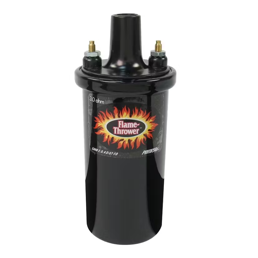
Pertronix (of course) recommends upgrading the coil to provide a more-powerful spark to the spark plugs all the time. For a typical 4 or 6-cylinder engine, they recommend their 3 ohm 40,000 Volt Flame Thrower coil. Their 3 ohm coil has been optimized to run with no external ballast resistor and a full 12 VDC power source (like the Pertronix Ignitor module). Optimizing the Pertronix Ignitor 3.0 ohm coil for 12 VDC and an installation on a 4 or 6 cylinder engine Keeps the internal coil temperature down with an internal design structure designed for optimum operation in conjunction with a non-V8 engine. For a V8 engine install, with its increased number of cylinders, has different coil needs. The 1.5 ohm coil is internally designed to be optimized for use with a V8 engine. Using the recommended Pertronix coil permits removal of the ballast resistor wire completely from the circuit, and simplifies the restructure of the ignition wiring in the vehicle.

Understanding the reasons for the original Corvair ignition wiring design allows the installer to properly install the Pertronix Ignitor module wiile retaining the original Delco coil. (This requires 12 VDC full time for the Ignitor module, while retaining the ballast resistor wire circuitry for the Delco coil). If the coil is to be upgraded to a Pertronix Flame Thrower 40,000 volt coil, the 3.0 ohm coil should be selected. This simplifies the wiring, and permits the bypass or removal of the ballast resistor wire completely.

These options are obviously often a point of confusion, and the incorrect choices of aftermarket components, or the incorrect installation and wiring modifications can lead to faulty operation. Pertronix engineers have tried to improve their written installation instructions and also their marketing catalog and documentation. but errors continue to be made.

The design flaw in the Pertronix Ignitor II module, which begins to fail at very slow idle speeds (as in a 6-cylinder Corvair with a Powerglide automatic transmission that slows the idle speed) adds to the confusion.

No, I don't work for Pertronix. I have a Powerglide-based Corvair using a Pertronix Ignitor (not Ignitor II), and that configuration, along with a 3 ohm performance coil and no ballast resistor wire works just fine! I chose a FAST XR-3000 ignition system for my Corsa convertible, just to give that brand and configuration a try too.

I hope this technical information and attempt at an explanation is helpful.
Brad Bodie
Lake Chatuge, North Carolina
Image 1966 Corvair Corsa Convertible
User avatar
sethracer
Posts: 30
Joined: Sun Dec 13, 2009 5:06 pm

Re: Melting wires, simple question

Post by sethracer »

Well, yes and No, Frank, on the plug gaps. I still suggest .035 on the Corvair, no matter which ignition.
This is worth a read: (from the Internet)

"Origins and Purpose of HEI:
The GM HEI system was not initially developed as a performance ignition system. Instead, its primary purpose was to effectively ignite increasingly lean fuel/air mixtures in emissions-controlled engines.
To meet emissions standards, the HEI needed to maintain consistent timing specifications over at least 50,000 miles without degrading.
One of the key criteria was to create a spark that could bridge a slightly larger spark plug gap than what a traditional points-based system could handle.
Larger Spark Plug Gap:
The HEI system was designed to fire off leaner fuel molecules. As fuel molecules decreased for leaner mixtures, there needed to be enough gap in the spark plug to ignite the burn in the combustion chamber.
To achieve this, engineers created “drivers” in the HEI module. These drivers increased the dwell charge time to the coil, allowing it to store more energy.
The result was that the HEI system could function correctly with a larger spark plug gap compared to a point system.
Engineers’ Experimentation:
During the development of HEI, some engineers decided to further increase spark plug gaps to fire off even leaner fuel mixtures.
Brands like Pontiac, Buick, Cadillac, and especially Oldsmobile opened up their spark plug gaps first to 0.065 inches, and later to 0.080 inches.
However, they made no changes to other distributor components to accompany these increased gaps.
Unintended Consequences:
Unfortunately, this decision led to a significant increase in warranty failures related to HEI modules and coils.
The failure rate reached alarming levels, especially for Oldsmobile vehicles.
The issue was traced back to heat/load-induced coil layer shorting and other issues caused by the larger spark plug gaps.
The Fix:
The solution was straightforward: reduce the spark plug gaps back down to the original 0.045 inches sizing.
Once this adjustment was made, the warranty coil/HEI module failures and problems ceased, and failure rates returned to pre-gap-increase levels.
In summary, while HEI systems can tolerate slightly larger spark plug gaps, pushing them too far can lead to unintended consequences. The original design parameters were carefully balanced to ensure reliable ignition while meeting emissions requirements12. So, when it comes to spark plug gaps, moderation is key!"
Corvair Enthusiast.
66vairguy
Posts: 4690
Joined: Tue Dec 21, 2010 3:44 pm

Re: Melting wires, simple question

Post by 66vairguy »

kmart356 wrote: Sun Apr 21, 2024 9:57 am
NMVair wrote: Sun Apr 21, 2024 9:06 am I'm glad your having a great conversation about coils. Interesting. But my alternator is only charging at between 12 and 12.5 volts
And the fan light is on. It must have been doing this all the while since the light has been on since I got a higher output alternator rebuilt for the car.
It should be charging at a higher voltage rate, correct?
But tye car starts and runs great.
I know because I checked it twice- IT IS WIRED AS I WAS TOLD! My question is will this slight lack of voltage cause the light to come on so bright???
Ok back to your coil conversation.
:assault:
Found this little tidbit after scouring the forum(s)

"The voltage should be between 13.7 and 14.7 volts. If it is not, there may be a fault in the alternator circuit."
Yes 13.7 to 14.7 is considered normal. Keep in mind as the battery becomes fully charged the voltage drops some. That is the reason for the range of charge voltages. Of course if the amperage demand is larger than what the alternator can supply the voltage drops - I SERIOUSLY DOUBT THIS IS YOUR ISSUE. It sounds like you are running off the battery only and the alternator is not turned on. As already stated by someone here, rev engine to 2,000 RPM (for a second) and see if alternator starts charging. If so you have one of those one wire conversion regulator packs in the alternator. If the alternator does not turn on, then the sense line could be open. If it is open the alternator might work (depends on regulator pack used) or it will shut off. This is to prevent "runaway" voltage output which can ruin a cars electrical components!!!! NEVER EVER CONNECT EITHER TERMINAL TO GROUND.

I'm assuming you have a 10SI internally regulated alternator. Make sure you have the warning lamp and sense lines to the correct places. See GM diagram and note 10SI terminal designations and diagram on pg 2 for sense and warning lamp connections.
Attachments
10-SI Delco_Alternator Sev. Bullt. 12-1-78.pdf
(1.15 MiB) Downloaded 3 times
Post Reply

Return to “Ask your Mechanical Questions here”