hesitation, no power after warmed up
hesitation, no power after warmed up
Hi, new to the forum and new 61 Monza owner, new to Corvairs. Car starts and runs fine with seemingly no issues initially. After being driven and warmed, shutoff, and then started again, car will hesitate and have no power to drive. Changed fuel filters, checked fuel pressure to carbs, checked electrical connections, didn't seem to be any vacuum leaks. Not sure of next step....Thx
-
terribleted

- Posts: 4584
- Joined: Sun Apr 18, 2010 2:36 pm
- Location: Atlanta, GA
- Contact:
Re: hesitation, no power after warmed up
Are the both choke plates fully opening when you push the choke knob all the way in?
Corvair guy since 1982. I have personally restored at least 20 Vairs, many of them restored ground up.
Currently working full time repairing Corvairs and restoring old cars.
https://www.facebook.com/tedsautorestoration/
Located in Snellville, Georgia
Currently working full time repairing Corvairs and restoring old cars.
https://www.facebook.com/tedsautorestoration/
Located in Snellville, Georgia
-
bbodie52

- Corvair of the Month

- Posts: 12143
- Joined: Mon Aug 06, 2012 12:33 pm
- Location: Lake Chatuge Hayesville, NC
- Contact:
Re: hesitation, no power after warmed up
 Since you don't have an automatic choke, the above was my first guess.
If your manual choke is fully releasing and opening the choke butterfly valves fully in each carburetor, a heat soak or fuel starvation issue in the carburetors would be another guess. But you seemed to have addressed that too. If you peer down the throat of each carburetor (engine off) and open the throttle, do you observe a squirt of gasoline into each carburetor throat from the accelerator pumps? Successful operation and function of the accelerator pumps is a quick way to confirm the presence of gasoline in each float bowl.vairLvr57 wrote: » Sat Aug 28, 2021 6:59 am
Hi, new to the forum and new 61 Monza owner, new to Corvairs. Car starts and runs fine with seemingly no issues initially. After being driven and warmed, shutoff, and then started again, car will hesitate and have no power to drive. Changed fuel filters, checked fuel pressure to carbs, checked electrical connections, didn't seem to be any vacuum leaks. Not sure of next step....Thx
Also, have you had the carburetors off of the engine recently? If so, were the plastic insulators reinstalled or replaced along with the gaskets at the base of each carburetor? If the insulators were accidently left off the carburetors can build-up too much heat from the cylinder head intake manifolds, which can cause the gasoline in the float bowls or fuel passages to boil and vaporize (a form of vapor lock).
- Carburetor Base Insulator and Gaskets.jpg (56.62 KiB) Viewed 1166 times

NGK Spark Plugs wrote:Avoiding Ignition Coil Failures and Returns
By: NGK Spark Plugs
July 1, 2017

https://www.aftermarketnews.com/avoidin ... d-returns/
Ignition coils can vary greatly in size and shape but share three common parts. These are the primary windings, secondary windings and a non-conductive or dielectric insulation material that separates the two windings. The insulation material is typically a dielectric resin that is applied in a vacuum, so air bubbles are not formed. Air bubbles can create a path for electricity inside of a coil, and lead to premature failure.
Coils fail for a variety of reasons including heat, vibration, or issues on the secondary side of the ignition system. Coils are commonly found bolted to the cylinder head, either on top or inside of a cylinder specific well. Excessive heat and vibration can cause the insulating material to break down and create internal coil failure. Worn secondary ignition components such as spark plugs or wires can cause a coil work harder, require more voltage, and therefore significantly reduce the operating life of the coil.
When a coil fails, it is possible the electricity created is unable to reach its destination, the spark plug. When this happens, the electricity created inside of the secondary windings looks for the path of least resistance to ground. This path is commonly found through the boot or body of the coil. Carbon tracking happens when oil, dirt, or moisture is electrostatically attached to the boot or insulator and creates a path to ground. When carbon tracking is found, the coil and corresponding plug should be replaced. It is also possible that a failed ignition coil can cause damage to the engine computer, or ignition control module.
Aftermarket replacement coils are often engineered to prevent common pattern failures found with the original ignition coils. These improvements can include improved dielectric materials that better insulate the secondary and primary coils. Also, improvements can be made to the design of ignition control module, so the unit is able to withstand greater levels of heat and vibration.
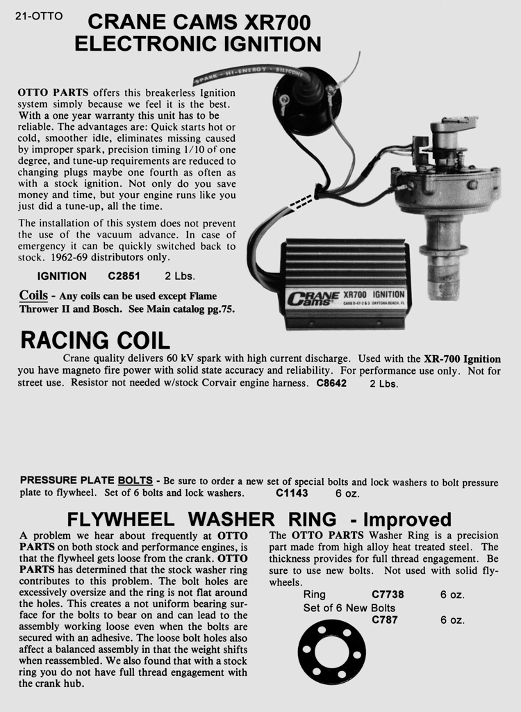
Are you running the original 1961-style distributor, or has it been changed to the 1962-1969 version (with the screw-type cap attachment). If it is the newer design, has it been upgraded with an electronic breakerless ignition system? Electronic components can sometimes fail with heat buildup.
1960-61 distributor on the right. Electronic breakerless ignition systems will only fit 1962-69 distributors.

Ted in Atlanta has a lot of professional Corvair experience. I remember his recommendation...
terribleted wrote:...I love my Crane ignitions. I have only ever seen one that had failed. Something I can not say about the Pertronix units where failure is somewhat common from what I have seen.
Corvair guy since 1982. I have personally restored at least 20 Vairs, many of them restored ground up. Full time restoration tech and mechanic. https://www.facebook.com/tedsautorestoration
Brad Bodie
Lake Chatuge, North Carolina
 1966 Corvair Corsa Convertible
Lake Chatuge, North Carolina
1966 Corvair Corsa ConvertibleRe: hesitation, no power after warmed up
Thx for the responses. Will check all of that, the choke plates are completely open. If it was a vapor lock, would it still start but run with possible hesitation or no power? It does start...
-
bbodie52
- Corvair of the Month
- Posts: 12143
- Joined: Mon Aug 06, 2012 12:33 pm
- Location: Lake Chatuge Hayesville, NC
- Contact:
Re: hesitation, no power after warmed up
Vapor lock can even come from overheated fuel lines, but if it were to be very hot carburetor bodies, the location of the overheated fuel within the carburetor body could impact fuel flowing through the main jet and into the venturi, but not so much in the idle circuits. It could be one or both carburetors. Or it could be something in the ignition system, such as an overheated coil. An overheated resistor wire in the wiring harness could have increased resistance and could be reducing voltage to the coil. An incorrectly installed Crane Cams XR-700 ignition module that is being powered directly with full 12VDC (by bypassing the resistor wire) can also overheat and begin to malfunction when hot. (You did not mention or describe your current ignition system configuration).
More troubleshooting and fault isolation techniques are needed to narrow it down. Tell us what you find and what you see.
More troubleshooting and fault isolation techniques are needed to narrow it down. Tell us what you find and what you see.
Brad Bodie
Lake Chatuge, North Carolina
1966 Corvair Corsa Convertible
Lake Chatuge, North Carolina
1966 Corvair Corsa ConvertibleRe: hesitation, no power after warmed up
Have not touched the carbs. The ignition system is the oem style points, which I have checked the point gap, plug gaps, timing, and dwell. Had a bit of trouble setting dwell, it remained a bit high.I just replaced the coil and it seemed to help, will be able to tell more tomorrow after another trial run. A couple of burning questions: does the system have a resistor? and the blue wire in the harness, is that what is for? There is an old (maybe resistor/maybe capacitor) on the coil mount with wire missing, is that the resistor? Thx....
-
bbodie52
- Corvair of the Month
- Posts: 12143
- Joined: Mon Aug 06, 2012 12:33 pm
- Location: Lake Chatuge Hayesville, NC
- Contact:
Re: hesitation, no power after warmed up
The wiring diagrams provided by Chevrolet in the 1961 Shop Manual were terrible. They appear to be engineering design sketches that were simply included in the shop manual to satisfy the need to publish something by th e tie the car arrived in the showrooms. The 1962-1963 and 1964 shop manual supplements were much better, in that the technical writers appeared to have had the time to redraw the 1961 wiring diagrams into detailed schematic diagrams that were much-easier to follow. I have included the 1962 diagrams below.
The combined schematic diagram is one where I took the shop manual supplement diagram individual pages and combindd hem together so that you can zoom in and pan around to trace circuits from end-to-end on a continuous diagram. Simply left-click the diagram to enlarge it, and click it a second time for maximum enlargement.
- 1962 Corvair Engine Compartment Wiring Diagram
- 1962 Passenger Car Combined Schematic
In the standard 1962 wiring diagram, there are two wires connected to the ignition coil positive terminal.
1) 20 Gauge Yellow Wire (20 Y) That can be traced back to the starter solenoid. This provides the coil with full battery voltage from the starter solenoid when the engine is being cranked. This higher voltage input to the coil primary boosts the coil output to the spark plugs during engine cranking to help the cold, slowly cranking engine to start. This 12 VDC battery voltage is turned off when the key is released, the engine stops cranking, and the starter solenoid is disengaged, leaving only the reduced voltage (about 7 VDC) from the resistor wire to feed the coil. (The reduced voltage has been determined to be sufficient to keep the engine running, while the reduced voltage also serves to reduce the heat buildup in the ignition coil and also prolongs the life of he ignition points by reducing burning and arcing that occurs each time the points open or close.
2) 20 Gauge White/Red/Black stripe (20 W/R/B) - This is a special 1.8 ohm resistor wire that connects the multi-pin wiring connector also to the coil positive terminal. Full battery voltage is fed form the ignition switch (in the ON position) via the
IGNITION SWITCH (C) >> 14DG >> 18DG >> 18BRN >> 20W/R/B >> COIL [+] TERMINAL
- EM Corvair Color Codes
The black wire on the negative side of the coil is connected to the ignition points. When the points are closed, the negative coil terminal is connected via the points (closed switch) to GROUND, and the coil primary winding is turned on to build a magnetic field. Each time the points open, the coil primary winding is turned off and the magnetic field collapses, which induces a voltage through the secondary coil winding. This is the high-voltage that causes a spark to jump across the spark plug electrodes to ignite the fuel/air mixture in the cylinder. Which cylinder is firing is determined by the rotor in the distributor, and which distributor cap terminal the rotor is connected to at that moment.
Here is an animated diagram of a four-cylinder engine using ignition points...
- Attachments
-
- 1961 Chevrolet Corvair Shop Manual - Section 8 - Electrical Systems.pdf
- 1961 Chevrolet Corvair Shop Manual - Section 8 - Electrical Systems
- (3.28 MiB) Downloaded 67 times
-
- 1962-1963 Supplement - Chevrolet Corvair Shop Manual - Section 8 - Electrical Systems.pdf
- 1962-1963 Supplement - Chevrolet Corvair Shop Manual - Section 8 - Electrical Systems
- (2 MiB) Downloaded 81 times
Brad Bodie
Lake Chatuge, North Carolina
1966 Corvair Corsa Convertible
Lake Chatuge, North Carolina
1966 Corvair Corsa Convertible-
bbodie52
- Corvair of the Month
- Posts: 12143
- Joined: Mon Aug 06, 2012 12:33 pm
- Location: Lake Chatuge Hayesville, NC
- Contact:
Re: hesitation, no power after warmed up
If you wish to measure the voltage output of the resistor wire, the wires must be conducting electrical current to obtain an accurate voltage measurement, and the engine must not be running at the time the measurement is being taken. The procedure is described below...
With the engine NOT RUNNING and the key ON, the battery voltage is approximately 12.5 VDC. With the engine running, you are adding the charging system to the mix, with the measured voltage close to 14.5 VDC. Also, if you are measuring the voltage at the coil, with the engine running the voltage is rapidly switching between the two states of the coil negative terminal (open and grounded), as the ignition system charges and discharges/fires the coil. The correct method for testing the voltage at the coil (as described in the XR700 instruction sheet at the bottom of Page 12) is with the coil negative terminal grounded (equivalent to having points closed) so that current is flowing through the coil. This measures the voltage divider circuit with the ballast resistor and the coil primary resistance both in the circuit and active. If the coil negative is not grounded, you will only measure battery voltage (12.5 VDC).

With the engine NOT RUNNING and the key ON, the battery voltage is approximately 12.5 VDC. With the engine running, you are adding the charging system to the mix, with the measured voltage close to 14.5 VDC. Also, if you are measuring the voltage at the coil, with the engine running the voltage is rapidly switching between the two states of the coil negative terminal (open and grounded), as the ignition system charges and discharges/fires the coil. The correct method for testing the voltage at the coil (as described in the XR700 instruction sheet at the bottom of Page 12) is with the coil negative terminal grounded (equivalent to having points closed) so that current is flowing through the coil. This measures the voltage divider circuit with the ballast resistor and the coil primary resistance both in the circuit and active. If the coil negative is not grounded, you will only measure battery voltage (12.5 VDC).
bbodie52 wrote:May 03, 2021 7:25 pm
In order to test for the presence or absence of a ballast resistor or resistor wire in the circuit, it is necessary to have an active circuit that includes the ignition coil. (The coil must be grounded at the negative terminal and ignition switch must be on).
CHECKING VOLTAGE:If there is no ballast resistor or resistor wire in the circuit, and the negative coil terminal is grounded, you should read full battery voltage at the coil positive terminal. If a ballast resistor or resistor wire is present in the circuit, the voltage will be reduced to approximately 7 V DC. (With more than one resistor in the circuit, including a ballast resistor wire and the resistance inside the coil primary, a voltage divider circuit is created. To properly measure the resulting reduced voltage, electrical current must be flowing through the circuit to ground. That is why it is necessary to simulate the closing of the ignition points, so that the negative coil terminal is grounded. When the key is turned to the ON position, battery voltage is applied to the coil through the coil internal winding and on to ground. Without a ground attached to the negative coil terminal, no current is flowing so the multimeter will always read battery voltage applied to an Open circuit. Grounding the coil negative terminal completes the circuit and allows the resulting voltage through the voltage divided circuitry to be measured.
- Turn the engine off and make sure the key is in the OFF position.
- Attach a 20 gauge or larger (thicker) jumper wire between the coil negative terminal and a clean verified engine ground. (This simulates ignition points CLOSED – grounding the ignition coil negative terminal).
- Using a Digital Volt Ohm Meter (DVOM, or Multimeter), set the meter to the 20 V DC scale. (Meter set to read a voltage between zero and 20 V DC).
- Attach the red lead of the meter to the positive terminal of the coil.
- Attach the black lead of the meter to a good clean engine ground. (This is necessary to measure the voltage at the positive coil terminal).
- Briefly turn the key to the ON position without cranking the engine and observe the meter reading. Do not leave the key in the ON position more than a few seconds or damage can be done to the module and coil. (This applies voltage to the coil positive terminal from the ignition switch, with electrical current flowing through the coil to ground via the temporary coil grounding wire).
- Readings between 12.4 and 10 V indicate sufficient voltage for proper ignition function. Reading less than 10 V could indicate the presence of a resistor wire, ballast resistor, for engine ground or corroded wires and connections.
BE SURE TO TURN THE IGNITION KEY OFF AND DISCONNECT THE TEMPORARY GROUNDING WIRE THAT WAS ATTACHED FOR THIS TEST TO THE COIL NEGATIVE TERMINAL. DO NOT LEAVE THE IGNITION SWITCH ON FOR A PERIOD OF TIME LONGER THAN NECESSARY TO TAKE THE VOLTAGE MEASUREMENT.
- Attachments
-
- FAST XR700 and XR3000 Installation Instructions.pdf
- FAST XR700 and XR3000 Installation Instructions
- (3.65 MiB) Downloaded 46 times
Brad Bodie
Lake Chatuge, North Carolina
1966 Corvair Corsa Convertible
Lake Chatuge, North Carolina
1966 Corvair Corsa ConvertibleRe: hesitation, no power after warmed up
Thank you very much for all that great information, I am on it. Cheers
-
bbodie52
- Corvair of the Month
- Posts: 12143
- Joined: Mon Aug 06, 2012 12:33 pm
- Location: Lake Chatuge Hayesville, NC
- Contact:
Re: hesitation, no power after warmed up
I forgot to mention the capacitor (condenser) that is often found on the side of the ignition coil. It was added to provide some degree of radio noise suppression, to reduce interference from the ignition system that could sometimes be heard on the old AM radio.
Also often found on the generator and/or voltage regulator.

Also often found on the generator and/or voltage regulator.
Brad Bodie
Lake Chatuge, North Carolina
1966 Corvair Corsa Convertible
Lake Chatuge, North Carolina
1966 Corvair Corsa Convertible-
joelsplace
- Posts: 2629
- Joined: Wed Oct 13, 2010 12:51 pm
- Location: Northlake, TX
Re: hesitation, no power after warmed up
I've found the coil capacitors connected to the negative side. That is wrong and will cause issues. I had a very erratic Spyder tach that was fixed by taking the capacitor off of the negative side of the coil.
160 Corvairs, 5 Ultravans and counting
Northlake, TX
Northlake, TX
Re: hesitation, no power after warmed up
Did you find the problem. I have the same problem
Re: hesitation, no power after warmed up
The original post was back in 2021. No reply on fix. You are new, and your post is vague with little about YOUR car. This forum has been hit by AI CHAT BOTS so unless start your own post with more about your car and location for help --- well gotta go!