Vacuum Reading
Vacuum Reading
I have a 1966 Corvair that is the 95 HP with automatic transmission and I was checking the tune up specs and they were dwell 34 and the timing was about 16 or 17 and I checked the vacuum at the carburetors and it was varying between 12 and 14 ".I just don't know what the vacuum should be at idle? Anyone have an idea what it should be? Thanks Jerry
-
bbodie52

- Corvair of the Month

- Posts: 11897
- Joined: Mon Aug 06, 2012 12:33 pm
- Location: Lake Chatuge Hayesville, NC
- Contact:
Re: Vacuum Reading
Here are a couple of YouTube videos i found that you may find to be useful. The information on the Uni-syn gauge is what i use to synchronize the Corvair carburetors.


 https://www.amazon.com/Uni-Syn-Carburet ... B073RPZKBX
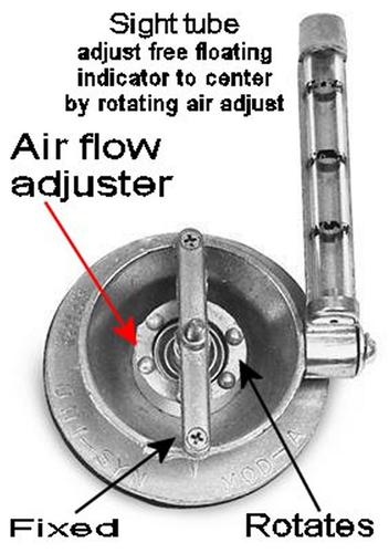
bbodie52 wrote: The Uni-Syn Carburetor Balancing Instrument is a tool that I remember as far back as the 1950s and 1960s. It was designed for use in multi-carburetor automobiles, motorcycles, etc. that were initially common in European vehicles, but were later found in American vehicles like the Corvair.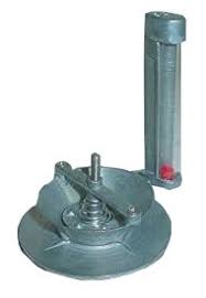

The Uni-Syn is an airflow gauge that must be calibrated to match the specific engine airflow moving through the carburetor throat. The flow control in the center of the Uni-Syn is mounted on a threaded pin. Rotating the flow control raises or lowers it, which increases/decreases the air gap, which impacts the air velocity passing the oriface that allows some airflow to pass through the gauge. With the Uni-Syn held firmly on the carburetor intake with the engine idling, the flow control is adjusted so that the plastic float is approximately centered in the glass sight tube. Once calibrated, the Uni-Syn can be moved back and forth between the two primary carburetors to compare airflow at idle. The goal is to play with the idle speed screws to get an even airflow level that matches between both carburetors, and at the same time produces the desired idle speed. Before fine-tuning this idle balance with a Uni-Syn, the ignition system, idle speed and idle mixture should have been adjusted following the standard procedures as described in the factory shop manual. The balancing step with the Uni-Syn gauge is added at the end of the tuning procedure to measure actual airflow though both carburetors at idle, and balancing that airflow using the airflow meter as a measuring tool, rather than simply relying on a physical balanced "calibration" using a strip of paper to detect initial contact between the idle speed adjustment screws and the carburetor linkage, followed by counting the screw turns needed to obtain the desired idle speed (and ensuring that the same number of screw turns are applied to each screw). That procedure achieves a fairly close initial setup. The use of the Uni-Syn airflow gauge as a final step ensures balance between the two carburetors by measuring actual airflow.
Once the balanced idle airflow and desired idle speed have been achieved, a similar procedure can be used to synchronize the airflow when the carburetors are held open at a faster engine speed by the throttle linkage. Again, the shop manual procedure can be used to set the initial mechanical balance between the two sides of the throttle linkage. The linkage segment connecting the accelerator pedal to the cross-linkage between the two carburetors is temporarily disconnected, and a turnbuckle is temporarily attached to hold the throttle opened against the pull of the throttle return spring.
The turnbuckle can be adjusted to hold the throttle open at approximately 1500 RPM. The Uni-Syn center flow control is readjusted to re-calibrate the float to a position somewhere in the center travel of the sight tube, based on the increased airflow through the carburetors at the higher steady RPM maintained by the turnbuckle arrangement. As with the idle synchronization procedure, the re-calibrated Uni-Syn is used to measure the airflow moving through the two carburetors. The goal is to fine-tune the threaded portion of the carburetor actuation linkage so that the same airflow reading is attained on each carburetor, but this time with the throttles held open by a pull on the throttle linkage, instead of by the setting of the idle speed screws. When the airflow has been balanced using the throttle linkage adjustment, the balancing procedure has been completed and the normal accelerator pedal throttle linkage can be reconnected.

TIPS & CLARIFICATION...
")
With the engine at idle, you want to open the Uni-Syn flow control as much as possible, but still keep the float in the sight glass at about mid-level. Then check the other carburetor, which you want to read the same flow rate. You may have to adjust the flow control a few times as you adjust the carburetor settings. Just remember to check each carburetor with the flow control set at the same point, and to keep the sight glass in the vertical to prevent the float from hanging up in the tube.
The wheel in the Uni-Syn venturi controls the flow through the tube, or in other words how high the bead is in the cylinder for a given engine speed. You need enough flow to not strangle the engine, and the bead works just as well in the lower third (which still lets good air flow through). Make sure the idle speed doesn't drop when you place the tool on the carb: if it does, open it up.
Before setting the carbs, make sure that the ignition is right: points and timing set, good wires and plugs. Poor running is often blamed on carbs when in fact it's a weak, retarded spark. Check the throttle shafts: loose ones let in air and lean the mixture, raising idle speed, as well as throw off the linkage action. Check the linkage that connects the carburetors. if it's loose, one will open before the other. Make sure there are no vacuum leaks.
With a twin carburetor set up, disconnect the linkage that connects one carburetor to the other. Set the idle speed with the linkage screws first. Use the Uni-Syn to check that each carburetor is drawing equally at idle. This may take a few tries until you get both drawing equally at the speed you want. Blip the throttle to see if they come back to those settings (worn throttle shafts can fool you). Set the idle mixture screws in accordance with the shop manual instructions. Check the balance again. Hook the linkage back up. If one carburetor now draws more, adjust the linkage until it's back to roughly equal.
Once the carburetors are drawing equally at idle, hold an engine speed: at about 1500 RPM. This checks that the mechanical linkage is pulling equally. You'll need to open up the Uni-Syn center wheel to draw more air and bring the bead down in the tube. If both carburetors are within a bead's thickness of each other, that's good. If one is definitely off from the other, the higher flow carburetor's linkage is being pulled more than the other. You'll need to figure out why that's happening mechanically to rectify it.
You need to backtrack a little...
The goal is normally to try to match the left and right carburetors as closely as possible. Rebuilding or replacing one carburetor while neglecting to do the same on the other side encourages something of a mismatch.
After checking for vacuum leaks (don't forget the Powerglide transmission vacuum modulator as a possibility), disconnect and plug the vacuum advance line that is coming from the right carburetor. (Make sure that the rubber hose is connected to the vertical vacuum tube on the right carburetor, and NOT the horizontal vacuum tube, which should be connected to the choke mechanism vacuum break unit on each carburetor). Temporarily readjust the carburetor idle speed screws to get the engine idle slowed down to about 700 rpm in NEUTRAL. This will ensure that the centrifugal advance mechanism in the distributor is not affecting the timing. Then recheck the points (dwell) with a dwell-tachometer and then the base timing setting with a timing light, and set them correctly for your engine, using the specs in the shop manual.
See Vacuum gauge viewtopic.php?f=225&t=10563
At this point, you will have confirmed that there are no vacuum leaks, and that the ignition system settings (dwell and timing) are correct. Reconnect the vacuum advance tube between the right carburetor and the distributor vacuum advance mechanism.
Following the procedures in the shop manual, the base (starting point) idle settings on each carburetor are to be established. With the throttle linkage at both carburetors disconnected from the cross linkage between the two carburetors, a narrow strip of paper is used like a feeler gauge by placing it between the idle speed adjusting screw and the carburetor throttle linkage. With the throttle closed, the idle speed screw is slowly backed away until it just releases its grip on the strip of paper. This establishes its point of contact with the throttle linkage. Then carefully turn the screw clockwise an a additional 1-1/2 turns to establish the idle speed preset. Perform this same procedure on the other carburetor. Then perform the idle mixture preset on both carburetors by gently turning the idle mixture screws all the way in so they just bottom-out in the carburetor. Then back each screw out counterclockwise 1-1/2 turns.
With the engine running, the correct idle speed for your engine must be established. With a manual transmission-based engine, the idle speed is set to the speed designated in the shop manual. This can be a starting point with the automatic transmission-based engine as well. Any adjustment made to increase or decrease the idle speed must be duplicated at both carburetors, so that the carburetor settings remain in sync on both sides. (A uni-syn gauge, or a vacuum gauge, if available, can be used to more-accurately synchronize the two carburetors so that they are each contributing an equal amount of airflow to the engine idle). With a Powerglide-based engine, the final idle speed must be set with the transmission in DRIVE, to load the engine with the resistance provided by the fluid coupling (torque converter). The goal is to achieve a slow, smooth and steady idle speed in DRIVE.
With the carburetor idle settings in sync, and the correct idle speed established in DRIVE, the last step is to reconnect the main throttle linkage between the two carburetors, and then the throttle linkage connection to the accelerator pedal. These procedures are described in the shop manual. There is an adjustment point in the linkage on the left side. The goal is to have both carburetors connected to the cross-linkage, without the linkage binding or holding either carburetor throttle open or impacting the idle speed. The link on the left carburetor is adjusted so that bot the right and left carburetor connections slip into the cross linkage. Finally, the adjustable link and throttle return spring is adjusted to slip into the cross link without changing the idle speed, so that the gas pedal permits opening the throttle fully but also allows the throttle to return fully to the idle setting.
Brad Bodie
Lake Chatuge, North Carolina
 1966 Corvair Corsa Convertible
Lake Chatuge, North Carolina
1966 Corvair Corsa ConvertibleRe: Vacuum Reading
OK thanks a bunch for the information. JERRY