Need some input
So my car did not have a heater when I bought it and recently i have installed one just looking for advise on running the control cables. I know that two go to the sides for the defroster but the ones that run to the back, how do they go through the tunnel to the heater box and fresh air. I have the accessories manual but does not really show. Do they go over the rear suspension crossmember?
Now on to the heater hoses that go from the back see to the rocker panels. Mine does not have any but I have purchased from clarks just wondering is there any easy tricks to running them?
Thanks again for any advice.
Jdflight
EM heater control cables and hoses
EM heater control cables and hoses
jdflight
61Monza aka Wilma

61Monza aka Wilma
-
terribleted

- Posts: 4584
- Joined: Sun Apr 18, 2010 2:36 pm
- Location: Atlanta, GA
- Contact:
Re: EM heater control cables and hoses
They follow the wiring harness thru the tunnel along the right side of the tunnel. They come out and go right up along the floor to the heater box connections. they do not best I can tell go thru any supports or clips after leaving the tunnel.
I just installed rocker hoses in a wagon 2 days ago. I made sure the rockers were clean and I "screwed" the hoses in from the rear end under the seat One side particularly took a lot of around and around of the pipe....the other side slid and screwed in more nicely and went faster. Could not get them thru and around the rear corner from the front.
I just installed rocker hoses in a wagon 2 days ago. I made sure the rockers were clean and I "screwed" the hoses in from the rear end under the seat One side particularly took a lot of around and around of the pipe....the other side slid and screwed in more nicely and went faster. Could not get them thru and around the rear corner from the front.
Last edited by terribleted on Thu Jan 25, 2018 12:40 pm, edited 1 time in total.
Corvair guy since 1982. I have personally restored at least 20 Vairs, many of them restored ground up.
Currently working full time repairing Corvairs and restoring old cars.
https://www.facebook.com/tedsautorestoration/
Located in Snellville, Georgia
Currently working full time repairing Corvairs and restoring old cars.
https://www.facebook.com/tedsautorestoration/
Located in Snellville, Georgia
Re: EM heater control cables and hoses
Terrilbeted
Thanks for the information. Would you or anyone else have a picture of how they are routed after they leave the tunnel. I seem to have a lot of extra cable. I am using a combination of cables from early models.
Thanks for the information. Would you or anyone else have a picture of how they are routed after they leave the tunnel. I seem to have a lot of extra cable. I am using a combination of cables from early models.
jdflight
61Monza aka Wilma
61Monza aka Wilma
-
terribleted
- Posts: 4584
- Joined: Sun Apr 18, 2010 2:36 pm
- Location: Atlanta, GA
- Contact:
Re: EM heater control cables and hoses
Maybe this will help.
Corvair guy since 1982. I have personally restored at least 20 Vairs, many of them restored ground up.
Currently working full time repairing Corvairs and restoring old cars.
https://www.facebook.com/tedsautorestoration/
Located in Snellville, Georgia
Currently working full time repairing Corvairs and restoring old cars.
https://www.facebook.com/tedsautorestoration/
Located in Snellville, Georgia
Re: EM heater control cables and hoses
You need the Assembly manual, not the Accessories manual...the path is diagrammed in the Factory Assembly Manual.
Nick
1964 Monza Spyder Convertible #435 - Rotisserie restored - SOLD ON BRING A TRAILER 4/30/2019 - Check out my restoration thread here: [corvaircenter.com]
Thanks to all the awesome CCF, CF, COG, and CORSA members who helped me with the restoration!
1964 Monza Spyder Convertible #435 - Rotisserie restored - SOLD ON BRING A TRAILER 4/30/2019 - Check out my restoration thread here: [corvaircenter.com]
Thanks to all the awesome CCF, CF, COG, and CORSA members who helped me with the restoration!
Re: EM heater control cables and hoses
Thank you for the picture and I do have the assembly manual just did not see that good a of a picture for how they existed the tunnel. Looks like previous owner might have ran a wire through some of the grommets in back where the cables belong.
Jdflight
Jdflight
jdflight
61Monza aka Wilma
61Monza aka Wilma
-
bbodie52

- Corvair of the Month

- Posts: 11894
- Joined: Mon Aug 06, 2012 12:33 pm
- Location: Lake Chatuge Hayesville, NC
- Contact:
Re: EM heater control cables and hoses


Brad Bodie
Lake Chatuge, North Carolina
 1966 Corvair Corsa Convertible
Lake Chatuge, North Carolina
1966 Corvair Corsa ConvertibleRe: EM heater control cables and hoses
Well here is an update with a couple of questions. Finally got the hoses through the rocker panels and was able to find some used air sperators (not sure of name) that diverts the air to the defroster. I started to install the cables but one broke after installing it on the driver side for the defroster. Now for some questions. Remember my car had the heater removed before I bought it.
1) I am assuming the carpet kit has to be cut for the rear vents to be installed under the rear seat, clarks carpet kit installed
2) the routing of the cables to the driver side does it go above the steering column or below?
3) Have the Clarks wiring harness for the heater controls does not sure how to install seems straight forward but not sure of the fan connection.
Thanks for any help in advance, looks like I will get this done just in time for summer.
jdflight
61Monza aka Wilma
61Monza aka Wilma
-
terribleted
- Posts: 4584
- Joined: Sun Apr 18, 2010 2:36 pm
- Location: Atlanta, GA
- Contact:
Re: EM heater control cables and hoses
Yes you must cut holes for the rear heat outlets if you plan to install them. Some people just seal the rear heat openings and leave the carpet to cover ....more heat to the front that way at least a little.
As far as I know the drivers side defroster cable runs along the floor under the carpet along the edge of the wheel hump area and continues under the column looping around to the control at that point.
Heater fan wire is a single wire that runs back to the fan (is part of the main body harness in heater equipped cars for sure) ... Not sure I understood that question.
Corvair guy since 1982. I have personally restored at least 20 Vairs, many of them restored ground up.
Currently working full time repairing Corvairs and restoring old cars.
https://www.facebook.com/tedsautorestoration/
Located in Snellville, Georgia
Currently working full time repairing Corvairs and restoring old cars.
https://www.facebook.com/tedsautorestoration/
Located in Snellville, Georgia
Re: EM heater control cables and hoses
Thanks for the info on the routing of the controls cables. I thought that was the cast but the assembly manual did not give a good reference. As far as the electrical I was referring under the dash the wiring harness from clarks seems a little off but I dont have an example of the original, it almost looks like the fan connect to a ground wire in the switch. I will go back to the wiring diagram.
jdflight
61Monza aka Wilma
61Monza aka Wilma
-
bbodie52
- Corvair of the Month
- Posts: 11894
- Joined: Mon Aug 06, 2012 12:33 pm
- Location: Lake Chatuge Hayesville, NC
- Contact:
Re: EM heater control cables and hoses
Somewhat confusing, the electrical wiring section 8 in the shop manual does not address the direct air heating system. It is covered somewhat in Section 11, DIRECT AIR HEATER (attached).
Left-click the image to enlarge it for better viewing or "Pan & Scan"...
- 1963 Corvair Passenger Car Combined Schematic
From Heater Fan Selector Switch Electrical
This link provides some material for installation and wiring of the Clark's heavy duty high-volume fan, if you are interested...

Anyone install a Hi Volume heater fan motor?
- Attachments
-
- 1961 Chevrolet Corvair Shop Manual - Section 11 - DIRECT AIR HEATER.pdf
- 1961 Chevrolet Corvair Shop Manual - Section 11 - DIRECT AIR HEATER
- (3.13 MiB) Downloaded 32 times
Brad Bodie
Lake Chatuge, North Carolina
1966 Corvair Corsa Convertible
Lake Chatuge, North Carolina
1966 Corvair Corsa ConvertibleRe: EM heater control cables and hoses
Hey everyone
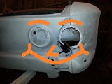
Thanks for all the help about to finish thing up and notice that I might be missing something. It looks like there should be a spacer between the control unit and where it mounts to the dash. I was wondering if someone would be able to verify that for me? When I go to bolt it up to the dash it seems to be rubbing.
Thanks for all the help about to finish thing up and notice that I might be missing something. It looks like there should be a spacer between the control unit and where it mounts to the dash. I was wondering if someone would be able to verify that for me? When I go to bolt it up to the dash it seems to be rubbing.
- Attachments
-
jdflight
61Monza aka Wilma
61Monza aka Wilma
Re: EM heater control cables and hoses
Was wondering if I could get me some help. I finally at a stage where I am trying to wire up the fan switch/ defroster resistor unfortunately/fortunately my car has had the wiring harness replaced so having difficulty hooking everything up. So in the mean time I have jumped the power side to the fuse box and connected the resistor then added a jumper from the fan. When I switch on the fan from low to med the resistor stars to heat up and smoke ( I don't have the resistor installed in the defroster vent) so is this indication that the fan switch is bad or because i have wired to the fuse box it not cutting off correctly? It starts to heat up and smoke right away though.a
I am using a clarks fan/accessories wire harness and defroster resistor. My fan switch is used and came with the controls since my car had no heater.
I am using a clarks fan/accessories wire harness and defroster resistor. My fan switch is used and came with the controls since my car had no heater.
jdflight
61Monza aka Wilma
61Monza aka Wilma
-
bbodie52
- Corvair of the Month
- Posts: 11894
- Joined: Mon Aug 06, 2012 12:33 pm
- Location: Lake Chatuge Hayesville, NC
- Contact:
Re: EM heater control cables and hoses
Your heater fan wiring difficulties are difficult to troubleshoot on paper. The 1961 shop manual wiring diagrams are a mess! I have come to believe that they simply published the engineering notes and wiring sketches in the shop manual instead of redrawing a combined wiring diagram in the final configuration. The 1962 wiring diagram is not much better. It looks like it was a first attempt at a consolidated wiring diagram, but they left some of it out! For example, if you start at the bottom of the 1962 wiring diagram and locate the HEATER BLOWER MOTOR, and then trace the 14 BRN wire back to the first multi-connector, you will discover that the wire goes nowhere! The other side of the multi-connector that is associated with the heater fan wire has nothing connected to it. At the other end, if you start at the fuse block and locate the 14 DG wire and trace it past the NEUTRAL SAFETY SWITCH, the wire continues to a connector labeled "HEATER TOTAL SYSTEM".
The diagram at the top is for a 1965 Corvair. It is not from the shop manual, but is a supplemental drawing that was done by way of explanation to show which combinations are in the circuit to control the fan at full speed, half speed, and low speed. At full speed, the resistor pack is bypassed and a direct connection is established between the power source and the motor. Low speed utilizes only one resistor, which minimizes current flow to the motor. Medium speed connects to both resistors, using both in parallel to increase current flow to the electric motor to produce a higher speed. I have to assume that there is a short somewhere that is causing the resistor pack output to be connected to ground instead of the electric motor. Such a connection would likely cause too much current to be drawn because of the motor missing from the circuit, and this would cause the resistors two overheat because the current drawn would exceed their capacity. If the circuit had a fuse in it I would guess that the fuse would blow to protect the circuit. But if you have bypassed the fuse and connected to the resistor pack to ground in some way there is no circuit protection and the result would be fuses that begin to burn up.
The wiring diagram at the top basically shows the goal you are trying to achieve with the heater control switch and the resistor pack. You may have to resort to using a multimeter (with the power source from the battery disconnected temporarily) to check for continuity at different switch positions to see which terminals provide a direct connect and connection to one or both resistor terminals. In this way you can test each segment of the circuit to trace the wiring to see where it goes and if it reaches the desired component. The direct connect from the switch should run directly to the motor input. The motor itself is grounded through the mounting case to provide the ground return to the battery negative terminal via the car chassis. (Does the full speed setting at the switch cause the motor to operate at full speed?) You should be able to trace the wire that is routed from the low speed position on the switch to one of the resistors in the resistor pack. When you move the switch to the second position (MEDIUM), the wiring connection from the switch should be routed to both resistors. The resistor pack output should be traceable back to the motor input.
The EM fuse block shown below may be a little confusing, because it shows two different fuses associated with the heater. I believe the 10 amp fuse is intended to be connected to the illumination lamps associated with the heater blower control switch and heater controls and the glove compartment lamp. The other fuse associated with the heater (total system) is a 20 amp fuse that powers the backup lights and the heater fan. So the 20 amp heater fuse is the one that is intended to power the heater fan motor. The 10 amp fuse is only intended to power the control lights.
- EM Corvair Fuse Block
It occurs to me that you might have the connections to the inputs (verticals spade connectors) reversed. (The output of the resistors is the horizontal spade connector). If the low switch setting is connected to the smaller resistor coil, it might overheat if it is the only resistor coil in the circuit that is connected to the low-speed switch setting. The resistor coil with a larger capacity would be the one that should be connected to the low-speed switch output. Having the wrong resistor coil connected to the low-speed switch output could be causing the resistor coil to overheat. Simply switching the two outputs of the heater switch to connect the low-speed wire to the larger resistor coil may eliminate the problem you are experiencing with the apparent overheating of the single coil that is operating by itself. The low capacity resistor coil may only be able to function properly when it is connected in tandem with the larger coil, thus sharing the load to the motor between the two resistors.
- Heator Resistor (1).JPG (22.42 KiB) Viewed 1328 times
- Heator Resistor (2).JPG (21.27 KiB) Viewed 1328 times
- Heator Resistor (3).JPG (23.78 KiB) Viewed 1328 times
- Heator Resistor (4).JPG (25.17 KiB) Viewed 1328 times
Brad Bodie
Lake Chatuge, North Carolina
1966 Corvair Corsa Convertible
Lake Chatuge, North Carolina
1966 Corvair Corsa Convertible-
terribleted
- Posts: 4584
- Joined: Sun Apr 18, 2010 2:36 pm
- Location: Atlanta, GA
- Contact:
Re: EM heater control cables and hoses
These resistors do get hot. They can get hot enough to possibly start a fire if combustibles like paper are touching them. That is why they are factory mounted in a duct or some other protected spot.
Corvair guy since 1982. I have personally restored at least 20 Vairs, many of them restored ground up.
Currently working full time repairing Corvairs and restoring old cars.
https://www.facebook.com/tedsautorestoration/
Located in Snellville, Georgia
Currently working full time repairing Corvairs and restoring old cars.
https://www.facebook.com/tedsautorestoration/
Located in Snellville, Georgia
Re: EM heater control cables and hoses
Brad
Thank you very much for all the help and information. I am going to relocate my jumper wire on the fuse block and see if that makes a difference. The fan runs just as advertised with all my jumper wires in place, so with the information that the resistor runs super hot I think I am going to save myself some time and run a new wire from the fan to the wiring harness then try and locate the right wire for the power connection from the original wiring harness before creating a new wire from the fuse block to the blower motor wiring harness. I will keep everyone updated, this is the last part of this project before I get her back on the road and it is becoming quite the monster.
Thank you very much for all the help and information. I am going to relocate my jumper wire on the fuse block and see if that makes a difference. The fan runs just as advertised with all my jumper wires in place, so with the information that the resistor runs super hot I think I am going to save myself some time and run a new wire from the fan to the wiring harness then try and locate the right wire for the power connection from the original wiring harness before creating a new wire from the fuse block to the blower motor wiring harness. I will keep everyone updated, this is the last part of this project before I get her back on the road and it is becoming quite the monster.
jdflight
61Monza aka Wilma
61Monza aka Wilma