This appears to be a Pertronix
FlameThrower II high performance (45,000 Volt) coil with a special 0.6 ohm primary resistance. (It is difficult to read the label in the picture). Removing the coil from its normal mounting position on the engine cylinder head, to the right of the distributor, and relocating to a mounting position on the car body perimeter frame is a good idea, as it is a cooler location that physically isolates the coil from direct contact with engine heat.
I have provided in 1965 Corvair engine compartment wiring diagram for you to refer to. However, the color codes for the wires may be somewhat different in the 1966 model year.
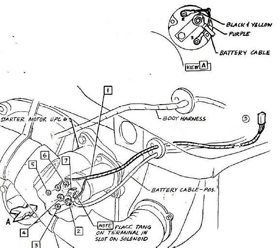
- 1965-1969 Corvair Engine Compartment Wiring Harness Starter Connections.jpg (80.88 KiB) Viewed 833 times
If you locate the ignition coil in the schematic diagram, you will see a wire labeled 20 B/Y (black/yellow) connected to the ignition coil positive terminal. This wire can be traced back to a two connector cable that leads to the starter solenoid. At this connector you will see that the 20 B/Y wire is spliced to two power sources — one that leads to the starter solenoid and provides a full 12 V DC to the ignition coil while the engine is being cranked by the starter, and the other wire (a special resistor wire labeled 20 W/R/B) which provides a reduced operating voltage of approximately 7 V DC to the ignition coil from the ignition switch. The purpose of this dual voltage arrangement was to provide maximum battery voltage to the ignition system while the engine is being started, to provide a higher spark voltage to each spark plug to enhance engine startup. As soon as the engine starts the operator releases the key, which discontinues the full 12 V DC being provided from the starter solenoid. This leaves only the reduced nominal 7 V DC for normal engine operation. The lower voltage was deemed sufficient for normal operation, while providing reduced voltage that prolongs the life of the ignition points contacts (reduced electrical arcing and burning). The lower voltage provided to the ignition coil primary circuit also helps the coil to run in a lower temperature.
In your photograph, the yellow wire is likely the wire that would be traced back to the two pin connector that ties to the starter solenoid and to the resistor wire. Unless the special resistor wire has been bypassed, this circuit provides continuous 7 V DC to the ignition coil positive terminal as long as the ignition key is in the ON position. The lower voltage is superseded by full battery voltage (12 V DC) whenever the starter solenoid is engaged.
You did not state which type of Pertronix ignition coil is installed in your Corvair. If it is a standard high-performance coil replacement, it would be designated by Pertronix as a FlameThrower 40,000 V canister coil. If it is used in conjunction with the Corvair standard resistor wire, the coil that was installed should have a primary resistance value of 1.5 ohms. If the resistor wire in the wiring harness was bypassed or removed, the ignition coil should be a 3.0 ohm version. This type of coil is compatible with standard ignition points or the Pertronix Ignitor breakerless electronic ignition system that triggers the coil using a magnetic pulse to control the ignition system, instead of the original ignition points and condenser.


 If the coil is a Pertronix FlameThrower II high-performance coil (as it appears to be in the picture), the maximum output is rated at 45,000 V. This coil has a special ultra-low primary resistance of only 0.6 ohms, and it is not compatible with the ignition points, or the standard Pertronix Ignitor electronic ignition system. The FlameThrower II ignition coil is only compatible with the special Pertronix Ignitor II electronic ignition system, which is compatible with standard ignition coils or will also tolerate the Pertronix FlameThrower II coil with its ultra low 0.6 ohms primary resistance. (This type of coil draws a high primary current level and would quickly destroy ignition points and would damage the standard Pertronix Ignitor electronic ignition module).
I know that all of these compatibility issues can be confusing, but knowledge of these rules are necessary when performing a complete ignition system upgrade using Pertronix components. The electronic ignition modules (Ignitor or Ignitor II) require a full 12 V DC to power the electronics module. Proper installation of either of these systems in the distributor would normally require bypassing the resistor wire in the Corvair wiring harness. If you are still running ignition points and condenser in your distributor, bypassing or eliminating the resistor wire would not be appropriate. The lower output FlameThrower ignition coil can operate with the reduced nominal 7 V DC provided by the resistor wire, but doing so will reduce the output spark voltage to the spark plugs to some extent. The high performance coil is designed to tolerate full battery voltage at all times during engine operation — to provide a higher spark voltage to the spark plugs. But if it is triggered by ignition points the voltage must be the reduced voltage provided by the resistor wire, or the ignition points will wear at an excessive rate.
The red wire that is connected to the positive terminal on your ignition coil could be a power lead that is connected to a Pertronix Ignitor or Ignitor II electronic ignition system in the distributor. If that is the case, the ballast resistor and your Corvair wiring harness may have been bypassed to provide the proper voltage to the electronics module. It may also be providing a full 12 V DC to the Pertronix ignition coil, which should be tolerable for this heavy duty coil. You should examine your Corvair wiring harness, distributor, etc. to determine exactly what was installed and how it was wired in your Corvair.
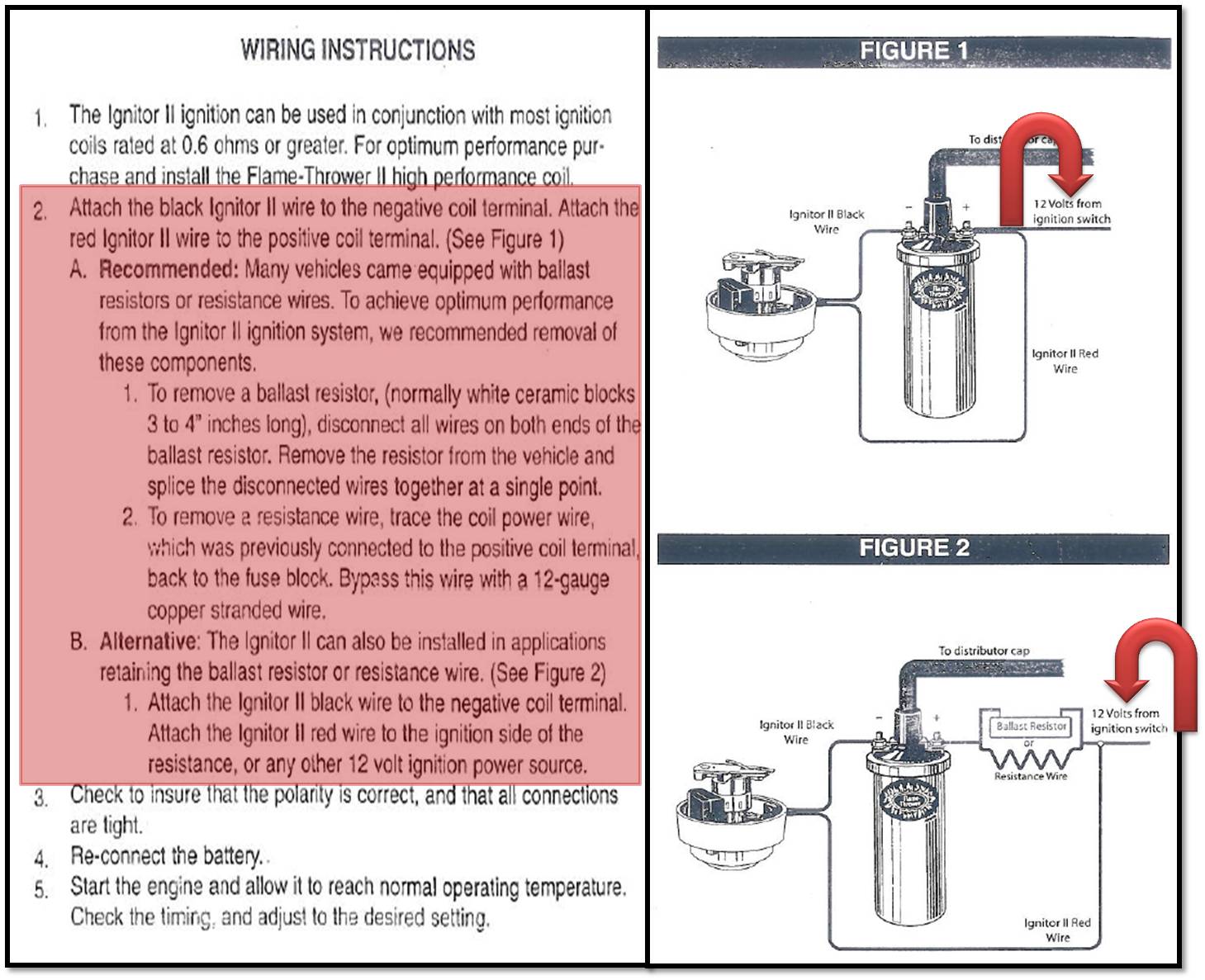
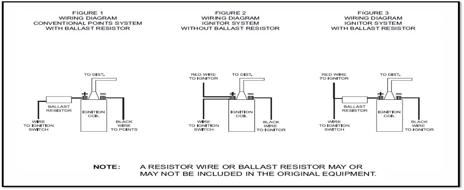
Since you indicated that you did not have the original Pertronix documentation, I have attached installation instructions for both the ignition coil and the electronics modules that would have been installed in the distributor. I have also attached some Pertronix catalogs. The website link to the Pertronix website is shown below. These catalogs and instruction sheets may be helpful to you. If you have any questions, please let me know.

 http://www.pertronix.com/
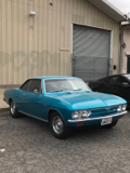


 1966 Corvair Corsa Convertible