Upon completion of an engine rebuild ('65 110 PG), what is proper procedure for doing a "bench" run? I have a large workbench where the engine is currently sitting. Can I bolt the torque converter inside the bell housing, put on the starter, and let it rip? Or do you have to attach the differential and transmission to run the engine?
Will it hurt the engine to run it while sitting flat on the oil pan?
Also, do I need to strap this thing down? Or is it going to try and jump around on the workbench while running?
Engine Rebuild Test Fire
-
terribleted

- Posts: 4584
- Joined: Sun Apr 18, 2010 2:36 pm
- Location: Atlanta, GA
- Contact:
Re: Engine Rebuild Test Fire
I would put the PG transaxle back on the engine and run it that way. The torque convertor is needed for the starter gear on it. The differential is needed to properly space the starter. The transmission is perhaps technically not needed at this point but fluids in the convertor will likely make some mess and the convertor will really need to be removed from the engine and assembled to the completed transaxle for final installation anyway. I have and automatic powertrain sitting on simple 4 caster moving dolly that I run regularly. Unless something is very wrong with a corvair engine they do not move around a lot. They will torque to the side with sudden hard acceleration. I make sure to support both sides under the heads to keep the unit from tipping (on the furniture dolly I use the lower shrouds sit nicely on the carpeted wood dolly and everything is nice and stable...I if want to rev it a bit I make sure I am countering its movement with my other hand).
I think I would want it closer to the floor than up on the workbench. Might be easier to work around all sides and to get onto a jack for installation after adjustments are complete.
I think I would want it closer to the floor than up on the workbench. Might be easier to work around all sides and to get onto a jack for installation after adjustments are complete.
Corvair guy since 1982. I have personally restored at least 20 Vairs, many of them restored ground up.
Currently working full time repairing Corvairs and restoring old cars.
https://www.facebook.com/tedsautorestoration/
Located in Snellville, Georgia
Currently working full time repairing Corvairs and restoring old cars.
https://www.facebook.com/tedsautorestoration/
Located in Snellville, Georgia
-
bbodie52

- Corvair of the Month

- Posts: 11908
- Joined: Mon Aug 06, 2012 12:33 pm
- Location: Lake Chatuge Hayesville, NC
- Contact:
Re: Engine Rebuild Test Fire
I think it would take you longer to configure a car simulator on your workbench than it would to reinstall the powertrain back into the car. And if you did reassemble the engine and transaxle on your workbench, and then you were able to successfully bench check the engine while it is still sitting on your workbench, you would then be confronted with a very heavy package that is high off the floor. You would have to find a way to get that heavy engine and transaxle assembly back down to ground level so that you could put it back in the car! You might as well get some help to manhandle the aluminum engine back down to ground level and then link it up with the transaxle. Then you can use a piece of plywood to protect the underside of the engine and the floor jack to lift the whole assembly and raise it back into the car.
Brad Bodie
Lake Chatuge, North Carolina
 1966 Corvair Corsa Convertible
Lake Chatuge, North Carolina
1966 Corvair Corsa Convertible
Re: Engine Rebuild Test Fire
If you're using a stock ignition don't forget to wire up a ballast resistor between the battery + terminal and the coil. Easy to overlook with the engine out of the car... You can pick one up at an auto parts store for about 8 bucks.
Alec Carlson
Dahlonega, GA
1965 Regal Red Corsa 4 Speed Turbo Convertible
Restoration "In Progress"...
Dahlonega, GA
1965 Regal Red Corsa 4 Speed Turbo Convertible
Restoration "In Progress"...
Re: Engine Rebuild Test Fire
Thanks fellas.
Acarlson - I have not changed any wiring at all, but I don't recall a ballast resistor... What does this look like so I can ensure it is still included? What purpose does it serve?
Acarlson - I have not changed any wiring at all, but I don't recall a ballast resistor... What does this look like so I can ensure it is still included? What purpose does it serve?
-
terribleted
- Posts: 4584
- Joined: Sun Apr 18, 2010 2:36 pm
- Location: Atlanta, GA
- Contact:
Re: Engine Rebuild Test Fire
The ignition resistor in the Corvair is built into the wiring harness. It is in the form of a resistance wire between the ignition and the coil. Its purpose is to drop the voltage at the coil and points to 6ish volts instead of 12 volts to prolong point life. If extended operation of the engine out of the car is desired it might be worth the effort to grab an ignition ballast resistor at the parts store to use in line with you hot wire feeding the ignition just to keep from arcing the points as much. If you are using an electronic ignition unit then IF it is designed to use with the stock Corvair wiring and reduced coil voltage then adding the resistor inline may be essential to keep from damaging the electronic unit. If an electronic ignition is in use that requires 12 volts and the resistance wire in the car has been bypassed for this reason then there is no reason to use a resistor inline in your hotwire to the coil. I would not worry about using an external ballast resistor to run the engine out of the car unless I was also using an electronic ignition that is made to run at the reduced voltage. If I was using the standard point I would simply hot wire the coil with 12 volts and operate the engine that way while out of the car. The worst case is that the points MIGHT get a bit pitted and would need to be replaced after, but, I have run and adjusted a number of engines on a hot wire for pretty good periods of time without incident. Afterall you are not driving the car across the country this way, just doing some relatively limited operation. The points normally operate at 12 volts momentarily by design when starting the car and the solenoid has the resistor wire bypassed by design delivering a full 12 volts to the coil, so its not like 12 volts is going to burn something up right away.
Corvair guy since 1982. I have personally restored at least 20 Vairs, many of them restored ground up.
Currently working full time repairing Corvairs and restoring old cars.
https://www.facebook.com/tedsautorestoration/
Located in Snellville, Georgia
Currently working full time repairing Corvairs and restoring old cars.
https://www.facebook.com/tedsautorestoration/
Located in Snellville, Georgia
-
bbodie52
- Corvair of the Month
- Posts: 11908
- Joined: Mon Aug 06, 2012 12:33 pm
- Location: Lake Chatuge Hayesville, NC
- Contact:
Re: Engine Rebuild Test Fire
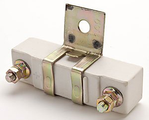
I have posted a 1965 Corvair engine compartment wiring diagram below. There is no physical ballast resistor in the engine compartment. Ballast resistors like the one pictured below were installed in 1962-1963 Corvair Spyders. When used, they were bolted to the perimeter frame in the engine compartment, near the ignition coil and distributor. All other Corvairs do have a ballast resistor, but it is in the form of a resistor wire that is integrated into the wiring harness. The special ballast resistor wire provides a resistance of 1.8 ohms. The Delco ignition coil adds an internal primary resistance of 1.28-1.42 ohms. The combined resistance of the two resistance values in series adds up to a nominal 3 ohms of primary resistance. This reduces the voltage across the ignition points in the distributor from the car voltage of 12 V DC to approximately 6-7 V DC. The reduced voltage is sufficient to power the coil and produce a spark at each spark plug that is sufficient for normal engine operation. But by reducing the voltage in this manner the operational life of the ignition points electrical contacts is extended, because burning and arcing that occurs each time the points open and close is reduced with the lower voltage. In addition, the ignition coil internal temperature buildup is reduced.
If you look at the wiring schematic and start at the ignition coil positive terminal (+) you can follow the wire (labeled 20 B/Y) back to a two pin connector near the starter motor. The 20 B/Y wire continues on the other side of the connector to a terminal on the starter solenoid (not depicted in this diagram). The wire is also spliced at the connector with another wire that is labeled 20 W/R/B. The short section of wire with this color code change is your 1.8 ohm resistor wire. It connects to a 12 pin multi connector. On the mirror image (firewall side) of the multi connector, the wire changes color again to 20 B/P. At this point the voltage is a full 12 V DC. It's source is the ignition key switch. When that switch is in the ON position, battery voltage is applied through the 20 B/P wire and continues through the multi connector to the resistor wire. The resistance provided by the resistor wire combined with the internal resistance of the ignition coil totals approximately 3 ohms, which reduces the voltage to a nominal 6-7 V DC (that can be measured with a multimeter at the ignition coil negative terminal) NOTE: This lower voltage can only be measured when the ignition points are closed. When the points opened, current will not be flowing through the ballast resistors, so the voltage would read full battery voltage.
The extension of the primary ignition circuit that connects with the starter solenoid (mentioned earlier) provides a method for temporarily increasing the voltage applied to the coil by bypassing the ballast resistors. This is desirable when starting a cold engine, as it provides a higher spark voltage to each spark plug to promote starting at the engine. When the ignition key is turned to START, the starter solenoid is engaged to crank the engine using the starter motor. At the same time a full 12 V DC is applied by the starter solenoid via the short 20 B/Y wire that is connected to the primary ignition harness. This higher voltage overrides the voltage reduced by the ballast resistor circuit and applies the higher voltage to the ignition coil positive terminal, but only as long as the engine is being cranked by the starter. The effect is to increase the spark plug voltage, but only while the engine is being cranked. Although the increased voltage is also temporarily increasing the intensity of the arcing that occurs at the ignition points, the effect is considered negligible for the short period that the engine is being cranked. The moment the engine starts the operator releases the key, and the ignition switch returns to the ON position. This disengages the starter solenoid and and turns off the higher voltage to the coil. What is left is the reduced 6-7 V DC provided to the coil via the ballast resistor. This lower voltage is sufficient to keep the engine operating once it has started.
Left click the image below to enlarge for better viewing…
Click on the link below to view complete, detailed wiring schematics for the entire car…
Corvair Combined Wiring Schematics
 http://www.corvairforum.com/forum/viewt ... 25&t=12968
If you look at the wiring schematic and start at the ignition coil positive terminal (+) you can follow the wire (labeled 20 B/Y) back to a two pin connector near the starter motor. The 20 B/Y wire continues on the other side of the connector to a terminal on the starter solenoid (not depicted in this diagram). The wire is also spliced at the connector with another wire that is labeled 20 W/R/B. The short section of wire with this color code change is your 1.8 ohm resistor wire. It connects to a 12 pin multi connector. On the mirror image (firewall side) of the multi connector, the wire changes color again to 20 B/P. At this point the voltage is a full 12 V DC. It's source is the ignition key switch. When that switch is in the ON position, battery voltage is applied through the 20 B/P wire and continues through the multi connector to the resistor wire. The resistance provided by the resistor wire combined with the internal resistance of the ignition coil totals approximately 3 ohms, which reduces the voltage to a nominal 6-7 V DC (that can be measured with a multimeter at the ignition coil negative terminal) NOTE: This lower voltage can only be measured when the ignition points are closed. When the points opened, current will not be flowing through the ballast resistors, so the voltage would read full battery voltage.
The extension of the primary ignition circuit that connects with the starter solenoid (mentioned earlier) provides a method for temporarily increasing the voltage applied to the coil by bypassing the ballast resistors. This is desirable when starting a cold engine, as it provides a higher spark voltage to each spark plug to promote starting at the engine. When the ignition key is turned to START, the starter solenoid is engaged to crank the engine using the starter motor. At the same time a full 12 V DC is applied by the starter solenoid via the short 20 B/Y wire that is connected to the primary ignition harness. This higher voltage overrides the voltage reduced by the ballast resistor circuit and applies the higher voltage to the ignition coil positive terminal, but only as long as the engine is being cranked by the starter. The effect is to increase the spark plug voltage, but only while the engine is being cranked. Although the increased voltage is also temporarily increasing the intensity of the arcing that occurs at the ignition points, the effect is considered negligible for the short period that the engine is being cranked. The moment the engine starts the operator releases the key, and the ignition switch returns to the ON position. This disengages the starter solenoid and and turns off the higher voltage to the coil. What is left is the reduced 6-7 V DC provided to the coil via the ballast resistor. This lower voltage is sufficient to keep the engine operating once it has started.
Left click the image below to enlarge for better viewing…
Corvair Combined Wiring Schematics
Brad Bodie
Lake Chatuge, North Carolina
1966 Corvair Corsa Convertible
Lake Chatuge, North Carolina
1966 Corvair Corsa ConvertibleRe: Engine Rebuild Test Fire
I would not sit the engine on the oil pan. I've pulled apart engines with bent up, or crushed oil pickups due to folks lifting the engine by the oil pan. The oil pickup bottom is JUST above the oil pan.
It's easy to take a piece of thin plywood and screw on a few blocks of 1/2" wood. One under the skid brace/rear motor mount bracket. The other two blocks on the lower bell housing extensions on each side.
Do prime the oil system before starting the engine so the bearings have a coat of oil and oil pressure comes up fast on start up. I use a distributor dummy shaft and a drill and keep the oil pressure up (and check it) while a helper rotates the engine a couple of times. Priming will also tell you if you have any leaks BEFORE you start the engine. The valve train should be manually oiled since the lifters will have to pump oil up the pushrod tubes and that takes a few moments. I usually use a break-in lube on the rocker balls and ends of the rockers (not too much).