Lumpy Idle

All Models and Years
User avatar
SeamusNZ
Posts: 88
Joined: Fri Sep 16, 2016 3:11 pm

Lumpy Idle

Post by SeamusNZ »

Hi all from New Zealand.

My '62 Spyder convertible rebuild is almost complete, however I do have a possibly major issue that I need help with. The engine I have rebuilt is non-turbo 110 hp.

The engine is running ok however it is idling very roughly.

The symptoms are:-

1. Very rough idle on both banks.
2. When I put a vacuum gauge on either bank, the gauge is extremely erratic. All over the place. The gauge steadies more as I lift the revs.
3. All indications are that it is a valve issue, however I have reset the rockers 3 times- the most recent being 1/4 turn past rattle. The heads and valves have been checked and reworked by a local engine reconditioning shop.
5. The ignition timing is advanced 6 degrees, however I am able to advance the timing considerably more without the engine pinking at any point.
7. Adjusting the mixture screw on either carburetor makes no noticeable difference to the idle quality.
8. Compression test - around 100psi on each cylinder.

Has anyone experienced a similar set of symptoms? And if so - what is the likely cause and remedy.

Any and all help is very much appreciated.

Kind regards...

SeamusNZ :helpsos:
64powerglide
Posts: 1604
Joined: Tue Mar 25, 2014 9:18 pm
Location: Kalamazoo Mi..

Re: Lumpy Idle

Post by 64powerglide »

Timing is set way to low, try 14 degrees advanced at 600 RPM, vacuum advance hose removed & plugged. Put some miles on it then recheck the compression, it should go up. :my02:
64Powerglide, Jeff Phillips

Kalamazoo, Mi..
66vairguy
Posts: 4617
Joined: Tue Dec 21, 2010 3:44 pm

Re: Lumpy Idle

Post by 66vairguy »

If the carburetors are working O.K. then it does sound like you timing is off. Verify timing of damper has not slipped and as already stated about 14deg at 600RPM. The other issue is a vacuum leak. I'm not sure if you have an engine with positive crankcase ventilation or just a vented to atmosphere, but there are different intake manifold crossover tubes depending on application.

If all else seems fine, then your camshaft may not be timed correctly. Matching the cam gear to the crank gear is not straight forward due to the ambiguous timing mark on the cam gears.
User avatar
SeamusNZ
Posts: 88
Joined: Fri Sep 16, 2016 3:11 pm

Re: Lumpy Idle

Post by SeamusNZ »

Hi thanks for your replies.

With respect to the crankcase ventilation system, this engine vents straight to the atmosphere. I am not sure what you mean by intake manifold crossover tubes. I don't think that this engine has any such tube. Both manifold intake ports are plugged????

Kind regards...

SeamusNZ
User avatar
bbodie52
Corvair of the Month
Posts: 11892
Joined: Mon Aug 06, 2012 12:33 pm
Location: Lake Chatuge Hayesville, NC
Contact:

Re: Lumpy Idle

Post by bbodie52 »

Make sure you check thoroughly for any signs of vacuum leaks, including split vacuum hoses, leaky vacuum break diaphragms, and a leaky Powerglide vacuum modulator (if you have an automatic transmission). The missing components such as the PCV system and the vacuum balance tube need to be obtained and installed to bring your engine into a normal configuration. The missing pieces can be found on eBay, Clark's Corvair Parts and the Corvair Ranch.

Image

The Positive Crankcase Ventilation (PCV) system was designed by engineers to deal with crankcase ventilation requirements in a wide range of engine operating conditions — full throttle, closed throttle, partial throttle, high RPM, low RPM, and everything in-between. The baffle plate and vents, the PCV tube, the PCV valve or fixed vacuum orifice that is connected to the vacuum balance tube, and the PCV breather connected to the air cleaner, are all part of a dynamic system design that is intended to function continuously during all engine operating conditions.

Image

Image

Image

I would recommend contacting a used parts source like the Corvair Ranch to obtain the missing components and to restore the originally engineered configuration to your PCV system.

The goal of the Corvair owner is to maintain the PCV system operation originally intended by GM engineers by cleaning the system (PCV Valve or Fixed Orifice) regularly. If the system is modified — as with the installation of custom air cleaners — the original tubing connections must be re-established with the newly installed custom air cleaners to ensure proper operation of the PCV system. A road draft tube is a poor substitute, as would be installing valve cover breathers or an oil filler cap breather. The properly operating PCV system minimizes crankcase contamination caused by normal piston blowby, which helps to prolong the life of the engine and ensure proper operation.

Try the Corvair Ranch...

:link: http://www.corvairranch.com/
Image

1079 Bon-Ox Road, ​Gettysburg, ​PA. 17325 USA
​Phone: (717) 624-2805
Fax us by the same number... ask us to hook up the machine
​Email: corvairranch@embarqmail.com
Our hours are Monday thru Friday 9 to 5, Saturday 9 to 12
or contact us for an appointment.


You should refer to the shop manual to see the correct configuration for your engine. The entire manual and many other Corvair technical references can be downloaded at no cost using the following link...

Common and Useful Corvair Websites
:link: viewtopic.php?f=225&t=6007
Brad Bodie
Lake Chatuge, North Carolina
Image 1966 Corvair Corsa Convertible
66vairguy
Posts: 4617
Joined: Tue Dec 21, 2010 3:44 pm

Re: Lumpy Idle

Post by 66vairguy »

SeamusNZ wrote: Thu Mar 02, 2017 12:13 pm Hi thanks for your replies.

With respect to the crankcase ventilation system, this engine vents straight to the atmosphere. I am not sure what you mean by intake manifold crossover tubes. I don't think that this engine has any such tube. Both manifold intake ports are plugged????

Kind regards...

SeamusNZ
Well now that may be one problem. The pad under the carburetor has a hole on each side, one is plugged, and the other has a tube that connects to the balance tube (head to head) with a rubber hose coupling (heads are the same so depending on which side the head is on the tube and plug are alternated at the pad) The carburetors on PCV engines were built to compensate for the "fixed" vacuum leak that vents the crankcase at idle. So without the manifold balance tube and it's fixed PCV vacuum leak you'll have a rich idle. The PCV systems used a PCV valve in 63, but the 110HP engine was a 65 or later so it used the fixed orifice PCV system. Since your car is a 62 (no PCV system) with a ???? year engine and who knows what year carburetors - well you've got some investigating to do. Bob Helt's carburetor book can explain what to look for. STILL a very erratic vacuum on BOTH heads at idle tends to suggest an ignition timing or a valve timing issue.

BTW the Positive Crankcase Ventilation system was developed for tanks during WWII (to keep water out of the engine while while crossing water hazards). GM investigated this system to make sure it had no negative impacts on engine performance and found no issues. In fact it kept dirt and water out of the engine and reduced external emissions by 50 PERCENT!! Of course this meant less "fumes" in the drivers compartment - not a bad thing!! First Calif. found the GM research and implemented PCV in 1961 for cleaner air and New York required it in 1962, by 1964 automotive manufacturers were installing PCV systems on most cars sold in the USA after discovering it also helped extend the service period of the engine motor oil ( The Big 3 started lengthening oil change periods in the early 60's to reduce ownership costs - which also resulted in increased ZDP in motor oil after an increase of camshaft failures due to extending the oil change intervals).
64powerglide
Posts: 1604
Joined: Tue Mar 25, 2014 9:18 pm
Location: Kalamazoo Mi..

Re: Lumpy Idle

Post by 64powerglide »

Here is a 64 October 63 built 110HP with a PCV setup, it vents into the right carb air cleaner, later 64 110 HP's vented into a single center air cleaner. You can see the PCV vent tube which curves around the back of the carbs & is connects to the intake.
Attachments
100_7389.jpg
100_7388.jpg
64Powerglide, Jeff Phillips

Kalamazoo, Mi..
User avatar
SeamusNZ
Posts: 88
Joined: Fri Sep 16, 2016 3:11 pm

Re: Lumpy Idle

Post by SeamusNZ »

Hi there,

Given that I have a direct vent system on my engine, and non-standard performance air cleaners on the carbs, should I run a rubber balance tube between the heads????

Kind regards...

SeamusNZ
64powerglide
Posts: 1604
Joined: Tue Mar 25, 2014 9:18 pm
Location: Kalamazoo Mi..

Re: Lumpy Idle

Post by 64powerglide »

If you don't have a tube coming out of the fan shroud make sure there are no open tubes on the back side under the carbs & reset the timing as described in previous replies. Can you post a photo of your engine? I assume you have a 3 or 4 speed trans. You can see from this photo where my balance tube is connected. If you have an open tube they need to be plugged.
Attachments
3-4-17 002.jpg
64Powerglide, Jeff Phillips

Kalamazoo, Mi..
User avatar
SeamusNZ
Posts: 88
Joined: Fri Sep 16, 2016 3:11 pm

Re: Lumpy Idle

Post by SeamusNZ »

Hi there,

There is a vent tube that runs from the top of the engine to underneath the engine. This expels fumes straight out yo the atmosphere?? Please find attached photos of my engine. I have connected a rubber balance tube between the head ports under each carburetor. They were previously plugged. I am running a 4 speed. Where does your balance tube (as per you photo) run to??

Kind regards...SeamusNZ
Attachments
image.jpeg
image.jpeg
image.jpeg
image.jpeg
User avatar
bbodie52
Corvair of the Month
Posts: 11892
Joined: Mon Aug 06, 2012 12:33 pm
Location: Lake Chatuge Hayesville, NC
Contact:

Re: Lumpy Idle

Post by bbodie52 »

It looks like someone replaced the left cylinder head at some point and used a head that was originally mounted on the right side of another engine. That would explain the vacuum tube facing the wrong way under the left carburetor. You would have to check the head casting numbers on the end of each head to determine if both heads are a match in compression ratio, combustion chamber volume etc. The hose you substituted should serve adequately as a balance tube.

The distributor has the appearance of some type of aftermarket custom distributor -- not sure what you have there.

A road draft tube was standard for crankcase ventilation on Corvairs from 1960 -1962.
Brad Bodie
Lake Chatuge, North Carolina
Image 1966 Corvair Corsa Convertible
User avatar
SeamusNZ
Posts: 88
Joined: Fri Sep 16, 2016 3:11 pm

Re: Lumpy Idle

Post by SeamusNZ »

Hi all from New Zealand.

With respect to the last post by Brad Bodie (thank you). The heads are definately a matched pair. I have obviously swapped the vacuum port aver to the other side??

The distributor is a Petronix Electronic distributor supplied by California Corvairs.

The lates information. I have completed two compression tests with the following results (which are quite erratic). The first test was a cold test with the throttle closed.

1. 118
2. 125
3. 120
4. 118
5. 119
6. 112

The second test was with a hot engine with the throttle open, the results being:-

1. 120
2. 120
3. 148 ???
4. 118
5. 130
6. 112

Honestly I am not too sure that I trust the gauge however the above are the only results I have.

Since I have installed a balance tube between the heads, retarding or advancing the timing now has a considerable effect on the idling quality of the engine, as does the mixture screws. This was not the case earlier. I have reset the timing to 14 degrees btdc as recommended.

Unfortunately the idle is still uneven, although it is not in jeopardy of stalling or anything like that.

Any thoughts???

Kind regards...SeamusNZ
User avatar
SeamusNZ
Posts: 88
Joined: Fri Sep 16, 2016 3:11 pm

Re: Lumpy Idle

Post by SeamusNZ »

Sorry Brad,

HEI electronic distributor. Nor Petronix.

Another dumb question.

With respect to obtaining an accurate vacuum reading, where should the vacuum gauge be plugged into. The choke pull off ports or the head ports (under each carburetor). Why I ask is that the erratic reading I referred to earlier was taken from the head ports???

Would there be a difference in the result??

Kind regards...SeamusNZ
User avatar
bbodie52
Corvair of the Month
Posts: 11892
Joined: Mon Aug 06, 2012 12:33 pm
Location: Lake Chatuge Hayesville, NC
Contact:

Re: Lumpy Idle

Post by bbodie52 »

Image

The HEI Distributor electronics requires a full 12 VDC power source to function properly. If you are powering the distributor electronics by simply tapping off of the positive terminal at the coil, and if the resistor wire in the Corvair wiring harness has not been bypassed, it is likely that you are only providing a nominal 7 VDC to the distributor. This could be causing the electronic magnetic pulse trigger circuitry inside the distributor to malfunction, which might explain the erratic engine operation.

Some Spyders utilized an external ballast resistor in the primary coil circuit that looked like the resistor below. If your 1962 Spyder has a physical ballast resistor, it should be bypassed when using the electronic distributor.
EM Corvair Spyder Ballast Resistor
:idea: The Pertronix Ignitor II electronic module is a magnetic pulse trigger similar to the module used in the HEI distributor (I believe). The Pertronix Ignitor II module has been reported as having a problem with providing a reliable ignition trigger at slow idle. In particular this caused a problem when using the Ignitor II in conjunction with Corvairs with automatic transmissions. The slow idle in DRIVE would cause the Pertronix Ignitor II to malfunction. If your distributor uses a similar electronic trigger module, it might also be experiencing an irratic trigger at slow idle.

The first diagram below shows the 1962 Corvair engine compartment wiring. The second diagram shows where you can splice into the 18 BRN wire on the firewall side of the multi-connector to pick up a full 12 VDC (switched by the ignition key switch) to power the coil and electronic distributor, bypassing the ballast resistor wire.

Left-click each image to enlarge for better viewing...
1962 Corvair Engine Compartment Wiring Diagram
1963 Corvair Pertronix Installation.jpg
The company that apparently began to offer these distributors for Corvairs first mentioned it on the Corvair Forum in 2014. Checking their website does not appear to indicate that they still make them for Corvairs.

:link: http://performancedistributors.com/
Brad Bodie
Lake Chatuge, North Carolina
Image 1966 Corvair Corsa Convertible
User avatar
SeamusNZ
Posts: 88
Joined: Fri Sep 16, 2016 3:11 pm

Re: Lumpy Idle

Post by SeamusNZ »

Hi there,

I have 12 volts going directly to a high performance coil.

Any opinion on my compression readings?

A lead on exactly where a vacuum reading should be coming from would also be helpful. Please refer to my earlier post.

Kind regards..

SeamusNZ
User avatar
bbodie52
Corvair of the Month
Posts: 11892
Joined: Mon Aug 06, 2012 12:33 pm
Location: Lake Chatuge Hayesville, NC
Contact:

Re: Lumpy Idle

Post by bbodie52 »

The attached section of the 1965 Corvair Shop Manual describes using a vacuum gauge in the INSTRUMENT CHECK-OUT section beginning on page ENGINE TUNE-UP 6-6. They describe connecting the vacuum gauge to both SPARK TUBES (vertical tubes) at the same time, for purposes of synchronizing the two primary carburetors with the throttle held open to 1100-1200 rpm.

Since the SPARK TUBES are intended for use supporting the distributor vacuum advance, they are blocked from manifold vacuum by the throttle butterfly at idle speed. As the throttle is opened, the spark port on each carburetor is exposed to intake manifold vacuum. The horizontal carburetor vacuum tubes are intended to be connected to the VACUUM BREAK devices. These horizontal ports are subject to intake manifold vacuum at all times (even at idle), so that the choke butterfly valves will be partially opened as soon as the engine has started.

The tune-up procedure in the 1962-1963 supplement and the 1964 supplement page 7-2 (attached) connects the vacuum gauge to the BALANCE TUBE, at the connector normally plugged or connected to the Powerglide automatic transmission vacuum modulator. This connection ties the vacuum gauge to both intake manifolds using the balance tube. The goal with this test is to adjust the idle mixture screws on both carburetors to obtain peak steady vacuum at the given idle speed. A second test is then described using the horizontal vacuum tubes that are normally connected to the choke diaphragms (vacuum break). This procedure differs from the procedure in the 1965 shop manual.

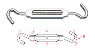
If a turnbuckle is used to hold the throttle opened at a steady 1100-1200 RPM, I don't think there is much difference between the vacuum measured at the vertical spark ports or the horizontal choke ports. With the throttle fully closed, the manifold vacuum measured at the balance tube and at the horizontal carburetor choke tubes should also be essentially the same. The difference between the horizontal and vertical carburetor vacuum tubes is controlled by the position of the throttle butterfly, which only uncovers the spark tube (vertical), exposing it to intake manifold vacuum, when the throttle is opened above the idle position.

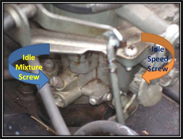
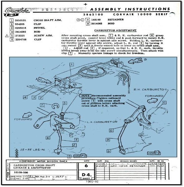
When synchronizing the carburetors at idle, and then at partial throttle, I normally utilize a UNI-SYN gauge, which measures airflow through the carburetor throat. The UNI-SYN allows me to balance airflow through both carburetors at idle, by adjusting the idle speed screws, and then at partial throttle (1100-1200 rpm), by holding the throttle opened with a turnbuckle and adjusting the throttle linkage at the left carburetor (adjustable linkage component [2] in the bottom diagram) to obtain a balanced airflow through each carburetor when the throttle linkage is holding both carburetors opened. (A static linkage adjustment is obtained first, as described in the shop manual tune-up section, using a strip of paper to determine the point where the idle speed screw just contacts the throttle linkage. 2½ turns are added to each idle speed screw to place the carburetor throttles at mechanical sync at idle. Fine tuning is then done with the UNI-SYN. Then the UNI-SYN is used to sync the throttle linkage at 1100-1200 rpm by adjusting the left swivel [2].

ImageImage

Image
Carburetor Idle Screws
Carburetor Throttle Linkage Diagram
Details of each carburetor component and sub-section is described in the attached DELCO ROCHESTER - Models H, HV Carburetor Service Manual.
Attachments
1965 Corvair Chassis Shop Manual - SECTION 6 - ENGINE TUNE-UP.pdf
1965 Corvair Chassis Shop Manual - SECTION 6 - ENGINE TUNE-UP
(2.92 MiB) Downloaded 14 times
1962-1963 Supplement - Chevrolet Corvair Shop Manual - Section 7 - Engine Tune-Up.pdf
1962-1963 Supplement - Chevrolet Corvair Shop Manual - Section 7 - Engine Tune-Up
(899.84 KiB) Downloaded 10 times
1964 Supplement - Chevrolet Corvair Shop Manual - Section 7 - Engine Tune-Up.pdf
1964 Supplement - Chevrolet Corvair Shop Manual - Section 7 - Engine Tune-Up
(931.65 KiB) Downloaded 8 times
DELCO ROCHESTER - Models H, HV Carburetor Service Manual.pdf
DELCO ROCHESTER - Models H, HV Carburetor Service Manual
(1.79 MiB) Downloaded 12 times
Brad Bodie
Lake Chatuge, North Carolina
Image 1966 Corvair Corsa Convertible
Post Reply

Return to “Ask your Mechanical Questions here”