With the ignition key
ON you should read about 7-8 VDC if you measure the voltage at the positive ignition coil terminal with the other multimeter lead grounded. (Do not measure between the coil Positive (+) and Negative (-) terminals. When the points are open the Negative (-) terminal is NOT grounded. It is only grounded when the points are closed). When you turn the key to
START to crank the engine, this voltage should jump to 12 VDC as long as the engine is being cranked. This is because the voltage to the ignition coil comes from two sources: the starter solenoid (12 VDC) and the ignition key (a reduced 7-8 VDC via a special resistor wire in the wiring harness). The higher voltage during cranking is intended to produce a "hotter" spark to help the engine start during cranking. As soon as the engine starts and the operator releases the key, the ignition switch returns to
ON and the higher 12 VDC ignition coil voltage feed from the starter solenoid is disconnected, leaving the lower 7-8 VDC operating voltage feeding the coil until the ignition key is turned to
OFF. The lower operating voltage at the coil is intended to reduce voltage and current across the ignition points during normal operation, which reduces arcing and prolongs the life of the ignition points contacts.
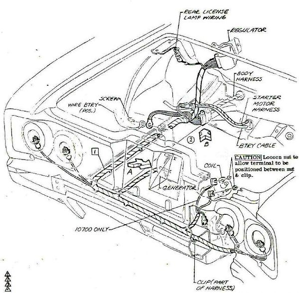
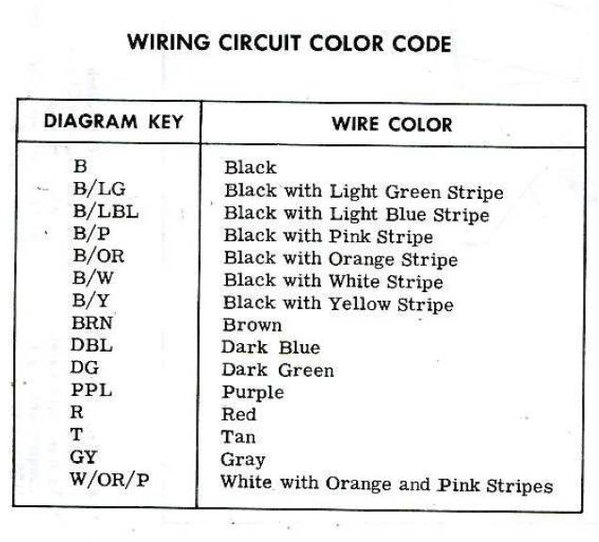
If you trace the 20 B/Y (20 gauge Black with Yellow Stripe) wire in the third illustration back from the positive coil terminal, you will see it connects to a two-connector terminal coming from the starter solenoid. The 20 B/Y wire continues through the connector to a terminal on the solenoid, and this is the source of the 12 VDC that is present ONLY during engine cranking. You will also see a splice at this connector with another wire (20 W/R/B) running to a 12 pin multi-connector (main engine compartment wiring harness). The other side of the multi-connector is connected to a 20 B/P (20 gauge Black with Pink Stripe) wire that can be traced through the other wiring diagrams back to the instrument panel and to the ignition switch source.
If you do not see a continuous voltage at the coil with the key
ON, but only see a voltage present at the coil when the engine is cranking, there could be a broken wire or, more likely, a corroded or loose connection in a multi-pin connector. To check this, try disconnecting the 12-pin multi-connector at the engine compartment harness (shown in the first two illustrations). Then, with the key
ON check for the presence of 12 VDC at the 20 B/P terminal in the multi-connector half that is connected to the harness coming out of the engine compartment firewall. If voltage is present at the 20 B/P wire pin but you did not see it present at the coil, check the multi-connector for a loose, bent, dirty, or corroded connection between the two halves of the multi-connector. Cleaning and straightening the pins, and then re-connecting the two halves of the multi-connector should correct your problem at the coil.
If there is no voltage present at the 20 B/P terminal in the engine compartment, you will have to trace further toward the instrument panel in the passenger compartment -- following the wiring schematic that ultimately leads to the ignition switch. Note that if other circuits in the car come on when the key is turned
ON, the problem is likely a broken wire or a bad multi-connector in the circuit, and NOT the ignition switch itself. The output from the ignition switch feeds several circuits when it is turned
ON, including the heater fan, instrument panel warning lights, radio, windshield wipers, etc. If those devices all work with the key
ON, power is coming from the switch to feed all of those circuits,
INCLUDING the ignition coil. Your task will be to locate where the voltage to the coil is being interrupted.


I hope that my explanation and the wiring diagrams and illustrations have increased your understanding of the Corvair ignition circuits, and will help you to successfully perform troubleshooting and fault isolation in your car. Please let me know if you have any questions.


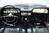
 1966 Corvair Corsa Convertible