Corvair Lakewood 61 - NL

Show of your ride, keep track of your project, watch as others progress on their projects
User avatar
TikiRalf
Corvair of the Month
Posts: 621
Joined: Tue May 24, 2011 1:07 am
Location: Valkenswaard - Netherlands - Europe
Contact:

Re: Corvair Lakewood 61 - NL

Post by TikiRalf »

61SuperMonza wrote: Mon Apr 13, 2020 2:03 pm I just spent some time going through the posts of your build. What a great job you're doing. I am very impressed with your perseverance. The documentation of your work is great. I wish I had documented my resto as you have. A great restoration is all in the details. When you add all the little things up the result is a stunning Corvair.
I can't wait to get my Monza out this summer. Reading your posts even got me out in the garage to do a little tinkering.
Waiting for summer in
Alaska,
Norm
:tu: Thank you for your kind words!!!!

Your Corvair is looking awesome to!

And yes i have been taken photo's of everything, maybe a little bit to much, but my though better to much pictures than non. Take a lot of pictures of your finishing Corvair! Its looking real nice! and i bet the scenery in Alasko is awesome to (from what I have seen on Discovery Channel :rolling: ) :woo:
61SuperMonza
Posts: 310
Joined: Mon Apr 29, 2019 1:51 pm

Re: Corvair Lakewood 61 - NL

Post by 61SuperMonza »

I thought you might like this picture. This was taken last August at the family cabin. My father has had this property for close to 40 years. This is interior Alaska.
Attachments
20190817_102941.jpg
First corvair in 1985
Have owned 4 corvairs since
65 Corsa coupe 180 turbo
66 Monza coupe 110 PG
66 Monza coupe 140 PG
61 Monza club coupe w/ 150 turbo
Anchorage,AK
User avatar
TikiRalf
Corvair of the Month
Posts: 621
Joined: Tue May 24, 2011 1:07 am
Location: Valkenswaard - Netherlands - Europe
Contact:

Re: Corvair Lakewood 61 - NL

Post by TikiRalf »

61SuperMonza wrote: Tue Apr 14, 2020 10:10 am I thought you might like this picture. This was taken last August at the family cabin. My father has had this property for close to 40 years. This is interior Alaska.
WHOAAAAA AWESOME!!!! is the cabin only access by airplane? What a neat view!

Someday i go check it out myself! Alaska looks so beautifull and i need some more stamps from the National Parks :rolling:

Thank you for sharing this picture! and if you have more of these pictures they are always welcome!
61SuperMonza
Posts: 310
Joined: Mon Apr 29, 2019 1:51 pm

Re: Corvair Lakewood 61 - NL

Post by 61SuperMonza »

IMG-20150318-00054.jpg
The only way there is airplane or snow machine. Floats in the summer and skis in the winter. Another picture in the winter.
First corvair in 1985
Have owned 4 corvairs since
65 Corsa coupe 180 turbo
66 Monza coupe 110 PG
66 Monza coupe 140 PG
61 Monza club coupe w/ 150 turbo
Anchorage,AK
User avatar
TikiRalf
Corvair of the Month
Posts: 621
Joined: Tue May 24, 2011 1:07 am
Location: Valkenswaard - Netherlands - Europe
Contact:

Re: Corvair Lakewood 61 - NL

Post by TikiRalf »

61SuperMonza wrote: Tue Apr 14, 2020 1:06 pm IMG-20150318-00054.jpgThe only way there is airplane or snow machine. Floats in the summer and skis in the winter. Another picture in the winter.
That is so awesome! i watch a program on discovery where to sell houses in Alaska, and some of the are only acces by airplane or boat or in the winter the snowmobile, like your place :tu: I cant imaging (pretty crowded overhere, houses everywhere). :coolphotos:
User avatar
TikiRalf
Corvair of the Month
Posts: 621
Joined: Tue May 24, 2011 1:07 am
Location: Valkenswaard - Netherlands - Europe
Contact:

Re: Corvair Lakewood 61 - NL

Post by TikiRalf »

Allright I'm ready to start with the last electric items for the engine. bbodie52, you give me already loads of information. I'm searching it all out and i'm getting lost. Electric is not my strongest point :doh:

"The Pertronix electronic module needs a full 12 V DC switched source to power it, but the coil still benefits from running cooler on the reduced voltage provided via the original factory ballast resistor wire circuit. What this means is that you will need to provide power to the Pertronix module that is still switched on and off by the ignition key, but you need to tap off of the circuit BEFORE the resistor wire comes into play. On the wiring schematic, you can splice into the circuit (18 BRN) before the multi-connector (near the firewall and below the voltage regulator)."

Image

This is what i have and found on my Lakewood the connector and the 1961 wiring diagram to (wel I try) understand what wire is going to where.
765.JPG
Compare to the above wiring drawing there is a different in color wires see picture, and I have a WHITE wire also.
766.jpg
766.jpg (130.8 KiB) Viewed 1181 times
I got a Purple and Brown wire in my connecter acros from each other like in the other wiring drawing. Is that the brown wire I need to put a T section in for the electronic module ?
If not can someone help me out where i can tap a 12V wire and run it to the Electronic Module please


Another Question i'm building in a Electric fuel pump, can i use the same wire or find it closer to the dash to provide also the 12V for the fuel pump ? I want to build in a hand switch (safety switch). It is easier to run 1 wire from the dash to the switch and from there to the electric pump.

Thank you for helping me out!!!! you all ROCK :guitar:
Last edited by TikiRalf on Sat Mar 06, 2021 4:50 am, edited 1 time in total.
joelsplace
Posts: 2004
Joined: Wed Oct 13, 2010 12:51 pm
Location: Northlake, TX

Re: Corvair Lakewood 61 - NL

Post by joelsplace »

Brad and I disagree on this point. Assuming you have an Ignitor 1 (black) just hook up the wires to the coil. Nothing else is needed. It will run fine on the reduced voltage and Ken Hand says that they are much more reliable connected this way. I have never had trouble with mine. The Pertronix instructions do tell you to run them on 12V. I do find it odd that they tell you to power it with 12V but the supplied wires are the correct length and have a connector that fits the coil.
I'll bet I have more Pertronix 1 ignitors running than anyone else and none of them are connected to 12V.
157 Corvairs, 5 Ultravans and counting
Northlake, TX
User avatar
bbodie52
Corvair of the Month
Posts: 11891
Joined: Mon Aug 06, 2012 12:33 pm
Location: Lake Chatuge Hayesville, NC
Contact:

Re: Corvair Lakewood 61 - NL

Post by bbodie52 »

:goodpost: :idea: :confused: :dontknow: I would recommend going with the voice of experience, and try wiring your Pertronix I module to the positive coil terminal — running it as recommended above on the reduced voltage. I have never owned a Pertronix unit, and was basing my comments on the Pertronix instructions. If experience shows that this Pertronix component tolerates the lower voltage reduced by the ballast resistor, why not give it a try? The Crane Cams optical trigger XR-700 module was designed to run properly on that reduced voltage, and in fact has been known to overheat if connected to 12 VDC. Electronic circuits can usually tolerate some range of input voltage, so perhaps the Pertronix I module has been found to work fine on a nominal 7 VDC voltage that is tapped from the ballast resistor circuit.

If you try it with the reduced voltage and you have problems, you can always run a temporary jumper wire to the coil positive terminal from the battery to see of that clears the problem (if the Pertronix unit is malfunctioning). Otherwise, just wire it as recommended by joelsplace and move on. I want to see your fantastic project car on the road!

============================================================

The schematic wiring diagrams in the 1961 Shop Manual are TERRIBLE! The text indicates that they are from the 1960 Corvair, and apparently were carried over to the 1961 manual to satisfy a need to post SOMETHING when the 1961 Shop Manual was published! But they are incomplete, fragmented into several functional circuits, hard to trace or follow, and fail to show the complete Primary wiring circuit from the ignition switch to the coil (including the two power sources for the coil primary: 12 VDC from the starter solenoid to the coil while starter solenoid is energized — key in START position; and nominal 7 VDC via the ballast resistor wire when the key is in the ON position). The latter always provides reduced voltage for normal coil operation, but the higher 12 VDC from the solenoid (when the key is in the START position) essentially bypasses the lower resistor wire voltage by providing higher voltage to boost the coil output voltage to the spark plugs to enhance cold engine starting during low cranking speeds.

The 1961 wiring diagrams look like developmental engineering sketches that were never really appropriate or intended for dealer, shop, or home mechanics. The shop manual technical writers finally produced decent (and more complete) wiring schematics in the 1962 supplement, and the format for those wiring schematics basically continued (with annual revisions) through 1969. In any case, the RED wire provides power to the ignition key switch, The PURPLE switch wire sends trigger voltage to the starter solenoid when the key is rotated to START, and the DARK GREEN wire provides switched power to all of the vehicle switched circuits that are powered with the key in the on ON or START position. The 1962/1963 diagrams show the DARK GREEN wire changing to BROWN along its path to the rear engine compartment multi-connector. For the coil primary circuit, it provides ignition key switched 12 VDC where it enters the multi-connector in the engine compartment, and it exits the other side of the multi-connector into the special resistor wire that drops the voltage to approximately 7 VDC to prolong the life of the points and to allow the coil to operate with lower voltage for cooler operation. (The starter solenoid voltage for the ignition coil comes directly from the battery, and is only sent to the coil when the purple wire has triggered the starter solenoid during engine cranking).
Brad Bodie
Lake Chatuge, North Carolina
Image 1966 Corvair Corsa Convertible
User avatar
TikiRalf
Corvair of the Month
Posts: 621
Joined: Tue May 24, 2011 1:07 am
Location: Valkenswaard - Netherlands - Europe
Contact:

Re: Corvair Lakewood 61 - NL

Post by TikiRalf »

:tu: EASY JOB! thank you bbodie52 & joelsplace for the info.
767.JPG
Next step fuel pump wiring and completing the heater system.
Last edited by TikiRalf on Sat Mar 06, 2021 4:51 am, edited 1 time in total.
User avatar
bbodie52
Corvair of the Month
Posts: 11891
Joined: Mon Aug 06, 2012 12:33 pm
Location: Lake Chatuge Hayesville, NC
Contact:

Re: Corvair Lakewood 61 - NL

Post by bbodie52 »

TikiRalf wrote:Another Question i'm building in a Electric fuel pump, can i use the same wire or find it closer to the dash to provide also the 12V for the fuel pump ? I want to build in a hand switch (safety switch). It is easier to run 1 wire from the dash to the switch and from there to the electric pump.
Why add a secondary electric fuel pump to an already fully functional mechanical fuel pump system? The factory Delco fuel pump has proven itself for decades of reliable operation in many thousands of Corvairs. (I have yet to have one fail!) Adding another pump in series only adds more complexity and another possible point of failure. Electric pumps are designed to be mounted close to the tank to pressurize the fuel line from the tank to the carburetors. The mechanical pump is designed to develop a vacuum in the fuel line from the tank to the pump, to pull fuel into the pump chamber. On the pressure stroke from the fuel pump, the push rod retracts and the spring inside the pump forces the diaphragm to push fuel to the carburetors, but will only do so if one or more open needle valves in the float bowl(s) is open to permit additional fuel into the carburetor float bowl. If the carburetor inlet valves are closed, the pressure spring in the pump will remain compressed as a fluid lock will exist between the pump outlet and the carburetors. This leaves the mechanical pump in an idle mode until the carburetors need more fuel. The large spring inside the fuel pump establishes the fuel pump outlet pressure.

Mechanical pump internal diaphragms seldom rupture or leak, and the internal one-way valves are simple and reliable. Common points of system failure are the two flexible rubber fuel lines in the path between the fuel tank and the pump. If either of these short flexible fuel lines develop a leak or crack in the hose, they are not under pressure so little fuel will leak out. Instead, a leak at the fuel line hose becomes a vacuum leak that lets air into the ine and prevents a vacuum from being created by the mechanical pump to pull fuel from the tank. (A leak at the tank end may allow fuel to drip on to the ground, pulled by gravity. A leak at the other end, near the starter motor, is elevated above the tank outlet, so it is unlikely that fuel will leak out at that point near the engine. A faulty hose will let air in, but fuel will generally not leak out.

There are short lengths of rubber fuel hose at each end of the long steel fuel line between the tank and the engine. If either one of the rubber fuel lines develops a crack or leak, the result will be an air leak that prevents the pump from forming a vacuum to pull gasoline from the tank (like trying to suck on a drinking straw that is spit open on the side). You might want to inspect the rubber hoses and clamps near the tank and next to the starter, to maintain them in good condition with the hose clamps secure.

Image


To remove and reinstall the fuel pump, be sure that you have installed it properly. It is important to ensure that the fuel pump is correctly seated and installed. There is a hole in the side of the pump shaft that the tapered bolt tip must seat into. If the pump is sitting too high and the bolt is simply pressing against the side of the pump housing, rather than seating inside the tapered hole, the pump push rod will not be doing its job. Fig. 57 in the shop manual page shows the tapered hole that the tip of the bolt fits into. This ensures proper installation and seating of the pump.
Image

ImageImageImage


:link: http://www.corvair.com/user-cgi/catalog ... ow_page=65
Clark's Corvair Parts wrote:We have only been able to locate 2 manufacturers of original style Corvair fuel pumps. Since 1973, we have consistently seen 1-2% of new fuel pumps fail. From about 1998-2001, the failure rate went to nearly 10%! We finally convinced the pump manufacturer that they were using the wrong diaphragm material! Currently, about 1%-2% of the fuel pumps continue to have problems. The problems have usually been seepage of fuel or complete failure resulting in no fuel or a rupture of the main diaphragm. The main supplier (C3403) is now using "antiwicking" diaphragms & has returned to all 3 diaphragms having fabric reinforced material. We've also added a pump from a 2nd supplier (C3403A). Our experience with both is nearly identical. A spare pump is always a good idea.

Rod Note
  • 1960–61 style pump must use the 1960–61 pump rod.
  • Most 1960–61 already have 1962–69 pumps.
  • 1962–69 style pump can be used on 1960–61 but the 1962–69 pump rod must then be used.
60-61 FUEL PUMP ROD-REPRO (3 5/8") **WILL ONLY WORK ON 60-61 FUEL PUMP
Corvair Fuel Pump Push Rod Length.jpg
Brad Bodie
Lake Chatuge, North Carolina
Image 1966 Corvair Corsa Convertible
User avatar
TikiRalf
Corvair of the Month
Posts: 621
Joined: Tue May 24, 2011 1:07 am
Location: Valkenswaard - Netherlands - Europe
Contact:

Re: Corvair Lakewood 61 - NL

Post by TikiRalf »

Why add a secondary electric fuel pump to an already fully functional mechanical fuel pump system?
Because I replaced the mechanical pump for a bypass plate (fake mechanical pump) and installed a electric fuel pump. I only need to put a wire to the pump and it is all set to go :tu:
User avatar
bbodie52
Corvair of the Month
Posts: 11891
Joined: Mon Aug 06, 2012 12:33 pm
Location: Lake Chatuge Hayesville, NC
Contact:

Re: Corvair Lakewood 61 - NL

Post by bbodie52 »

OK. Here is some electric fuel pump installation advice from a non-Corvair guy who enjoys custom cars and hot-rod building...
how-to-build-hotrods.com
Electric Fuel Pump: How to Do It Right

http://www.how-to-build-hotrods.com/ele ... -pump.html


Want an electric fuel pump to last forever and work right? We're going to show you how to install it and wire it up the correct way!

Ok, let's talk about electric fuel pumps. There is a lot of confusion and misunderstandings about them. There is also a lot of potential danger when people don't do it right because they don't know the right way to plumb them in or wire them...

So, let's break it down:

When do you need an electric fuel pump?

Is an electric fuel pump reliable?

How do you keep an electric fuel pump safe?

How should you wire an electric fuel pump?

-When do you need an electric fuel pump?

Usually, a mechanical pump is preferred over an "aftermarket" electric pump. They tend to be more reliable. However, sometimes that won't work.

In my old '47 Chevy, the engine I had swapped in had an issue. The crossmember was in the way of the mechanical pump. So, I ran an electrical pump and had many trouble free miles.

Sometimes, people will plumb them inline with a mechanical pump to add more volume and pressure. This is more for a full on drag car though...

-Is an electric fuel pump reliable?

Yes they are. Hey, there's about a billion cars running around right now with them. All new cars have them.

With aftermarket pumps though, YOU have to install them. That's where some problems can start.

We're here to show you the right way to do it!

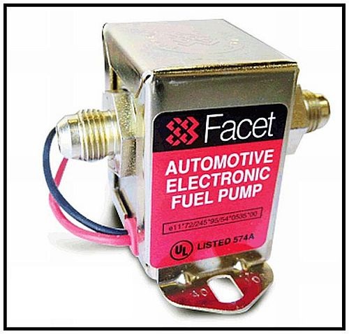
So, what do I use? For a stock or performance street car, I like these Facet/Purolator pumps from Napa. They are quiet, and work well.


Image


A lot of people complain about some aftermarket pumps being junk, but usually there is a reason they go out. It's often the way the person installed it. There are a few things that kill them.
  • Do not run them dry.
  • Always run a filter before the pump.
  • Keep them as close to the tank as you can. Electric pumps push fuel much better than they can pull it.
  • Mount them away from heat sources such as exhaust.
  • Electrical power to them is everything. You must have the correct wire size to it. A relay is preferred. You may be getting the proper voltage to it, but not enough amps. Remember, the longer the run the more the power will drop.
  • Also, the grounding of it is critical. Many people will scrape the area where they mount it, or even add a ground wire. However, they forget that they don't have a good ground from the body to the frame or to the engine. This will kill pumps real quick.
Tip: Screw into metal to ground, not through it. "Star" washers are your friends...

Preferably, run a ground wire to the front. Many professional auto electricians will run ground wires from a unit to a common grounding point in an older car, just like in a fiberglass car. That way, there is no question if your ground is good, and it's just 1 extra wire...

Once, a buddy and me were going to a show in his '26 Buick roadster. It was built much like a T-bucket and it had an electric fuel pump. It was wired in correctly, and grounded by screwing into the frame by the pump. We were about 50 miles out, and the pump quit...

Hmmmm...

What happened was the older metal of the frame simply wasn't carrying the current well enough. The pump overheated and shut down.

Fortunately, he had some extra wire and we screwed one end to the ground wire at the back and ran it to the front where we attached it to the negative side of the battery.

The pump started back up after it cooled down and we were trouble-free all the way there and back. When we got home he wired it in neatly and never had a problem after that...

-How do you keep an electric fuel pump safe?

Electric fuel pumps can be dangerous?

Yep, without some way to automatically shut them off, they can be VERY dangerous.

But they don't have to be.

If something lets go in your engine bay like a fuel line, the engine will eventually quit. However, if you don't have a way to automatically shut off your electric fuel pump you will keep spraying raw fuel all over your hot engine and wiring.

Also, in a crash, your pump can continue to run feeding a fire if you don't have a way to stop it.

Note: Never mount an electric fuel pump in an enclosed area such as the trunk or interior space...

OK, so how do I do it right?

The easiest way is to use an oil pressure switch. The switch will stop the pump whenever the oil pressure in the engine goes away. So, whenever the engine is off, the pump will turn off automatically.

Some switches just do that. But how do I get the pump to run when I'm trying to start the motor and the oil pressure's not up yet?

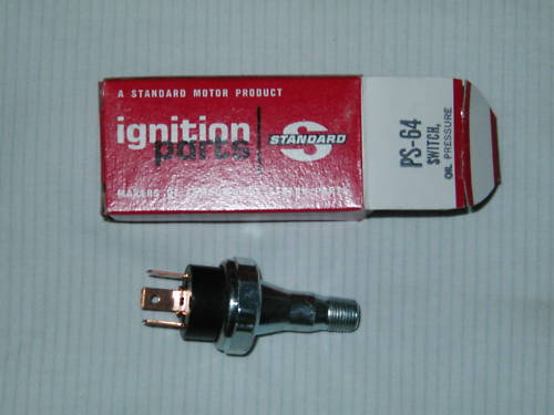
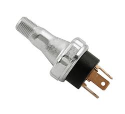
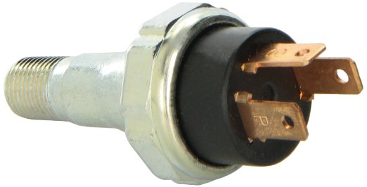
You use a three prong switch like this Standard Ignition PS-64:

Image

The switch will also let the pump run when you hit the starter because the engine doesn't have oil pressure yet.

Image

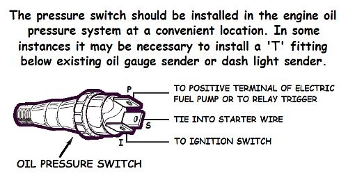
One wire goes to the pump, one to the start circuit, and the other to the ignition circuit. So, when there is no oil pressure, the switch connects START to PUMP, and as soon as you start cranking it runs the pump. When the oil pressure comes up, the switch connects IGN to PUMP, for normal running. When oil pressure goes away (because you just hit that rock and tore the pan off the engine, for example) it again connects START to PUMP, and disconnects IGN from PUMP, so the pump shuts off.

Don't worry, it's easy to wire...

-How should you wire an electric fuel pump?

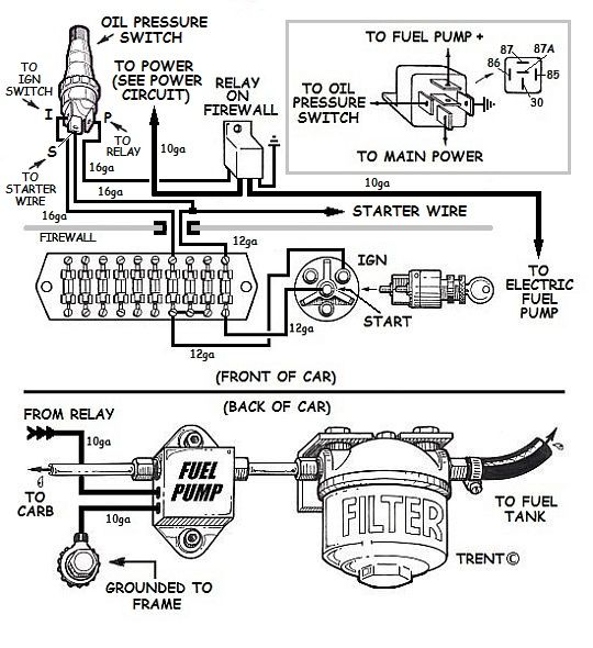
Since you need the fuel pump back by the tank and at the same level as the fuel or lower, that usually means you're going to have a long run of wire. So, you need to have really good wiring going back to it. Wiring that will carry enough current. Running the current through your ignition switch isn't a good idea since it's probably already overloaded, and will kill the voltage. That will kill the pump. However, it's nice for convenience. That's why a relay is really good to use.

It lets the ignition switch activate the pump, while keeping the power from having to run through it. It will keep your pump alive and happy because it is getting full voltage. A good way is to mount a relay beside a power distribution block on the firewall (see Improved Power Circuit) and get the power from there.

Here is a diagram on how to wire and plumb your pump:

Image

Since the oil pressure warning switch already occupies the threaded oil port next to the alternator/generator, an alternate location may be needed for the fuel pump safety switch. Clark's Corvair Parts has this covered with their ADAPT-A-BOLT...

:link: http://www.corvair.com/user-cgi/catalog ... nd_page=28
Part number C7521: ADAPT-A-BOLT-STOCK FILTER* IF USING W/ OIL TEMP SENDER-NEED TO DRILL ADAPTOR DEEPER

Weight: 0 lbs 6 oz
Catalog Pages(s): 28
Price: $ 24.05

Image

Airtex OS75 il Pressure Switch
:link: https://www.amazon.com/dp/B0027I8CU8?ta ... prdg2_eoh1

Image

Image

Image
Brad Bodie
Lake Chatuge, North Carolina
Image 1966 Corvair Corsa Convertible
User avatar
TikiRalf
Corvair of the Month
Posts: 621
Joined: Tue May 24, 2011 1:07 am
Location: Valkenswaard - Netherlands - Europe
Contact:

Re: Corvair Lakewood 61 - NL

Post by TikiRalf »

:tu: Thank you bbodie52 :tu: let me figure this out!

Thats a awesome safety item!! with the oil presure switch!

Allright, let me check the local autoparts store overhere. Because amazon wont ship to the Netherlands.
User avatar
bbodie52
Corvair of the Month
Posts: 11891
Joined: Mon Aug 06, 2012 12:33 pm
Location: Lake Chatuge Hayesville, NC
Contact:

Re: Corvair Lakewood 61 - NL

Post by bbodie52 »

There are several brands of fuel pump safety switches that can be obtained from multiple sources, including eBay. Some USA sources are shown below, but perhaps you can find a suitable European source.

Unfortunately the fuel pump safety switch does not include an oil pressure warning light function to keep your oil pressure warning light working. The Adapt-a-Bolt adapter offered by Clark's (shown in an earlier post) allows the fuel pump safety switch or the oil pressure warning switch (or an oil pressure gauge sending unit) to be mounted at the oil filter mounting bolt location.


The Airtex oil pressure safety switch stops the electric fuel pump when engine stops to prevent continued fuel delivery through the system in the event of an accident. This is an important safety feature when installing a universal electric fuel pump. This switch is designed for use with any universal in-line electric fuel pump.
ImageImage
The use of an oil pressure switch is a good choice. One way to provide safety is by using an Airtex OS-75 or a Standard PS-64 switch. These switches have three connectors. One provides power the pump, one gets power from the ignition switch, and one is connected to the starter solenoid so the pump will run while the engine is cranking. The cost of these switches is in the $12 to $15 range

Image
HOLLEY FUEL PUMP SAFETY PRESSURE SWITCH
The Holley P/N 12-810 fuel pump pressure safety switch is another alternative. Working Pressure range is 2-100 PSI.


Airtex Oil Pressure Safety Switches

:link: https://www.summitracing.com/parts/atx- ... gL-AfD_BwE

Mr Gasket Fuel Pump Safety Switch 1/8" NPT

:link: https://www.jegs.com/i/Mr-Gasket/720/7872/10002/-1

Holley Safety Fuel Pressure Switches 12-810

:link: https://www.summitracing.com/parts/hly- ... gJjSfD_BwE

:link: https://www.jegs.com/i/Holley/510/12-81 ... gL9V_D_BwE
Brad Bodie
Lake Chatuge, North Carolina
Image 1966 Corvair Corsa Convertible
User avatar
TikiRalf
Corvair of the Month
Posts: 621
Joined: Tue May 24, 2011 1:07 am
Location: Valkenswaard - Netherlands - Europe
Contact:

Re: Corvair Lakewood 61 - NL

Post by TikiRalf »

At the local parts store, they could order the Oil Pressure Safety Switches but it was €67,95 = $73,87 (brand unknow, same specs as the Airtex Oil Pressure Safety Switches OS75)

Compare to the Oil Pressure Safety Switches on the USA market it was pretty pricy.

I'm searching online on the Dutch and Europe market, but only find 1 hit (in the Netherlands). the Holley one: https://www.gooze.com/6205/hly-12-810-h ... witch?c=21

Price is $48,92 total (better than the local shop).

I'm going to do one more search tomorrow for a 3 point connection oil pressure safety switch, but there are not that many out there unfortunately.

Shipping from the USA (from Summit, Amazon) is around $35-40, so if i can not find it cheaper the best option is the Holley one from the Dutch shop.
User avatar
TikiRalf
Corvair of the Month
Posts: 621
Joined: Tue May 24, 2011 1:07 am
Location: Valkenswaard - Netherlands - Europe
Contact:

Re: Corvair Lakewood 61 - NL

Post by TikiRalf »

Ordered all the parts overhere in the Netherlands :tu: It will be here next week.
Time to work on the heatersystem, and after that we can fix the pump!

more updates comming soon!
Post Reply

Return to “Member's Rides, Projects, and Builds”