A place to preserve the past, present and future of the Corvair. An ever evolving knowledge base made up of Corvair Enthusiasts from all over the world. (Note: no ads for logged in members).
So I was curious as to what a turbo fuel filter looked like inside that made it so special. I knew that it had a bypass but didn't know how it was implemented. Well as I promised I found an old one and dissected it.
In the first picture we have the can on the left with it's cover next to it. The cover is the inlet. On the can we have the outlet side (filtered side) and the return tube.
Next you see the paper filter. The hole on the filter fits onto a tube with a gasket inside the can. The next part is a retaining clip that has ears that act as springs that keep the filter tight against the tube and gasket in the can side.
From this picture you can see inside the can with the tube in the center and circled in yellow is the small hole that allows the unfiltered fuel to bleed back to the tank.
I know it isn't very high tech but it worked back in the day. Today we use fuel pressure regulators that have a return fitting and separate fuel filters.
Well I hope that has satisfied your curiosity, I know it has mine.
toytron wrote:So I was curious as to what a turbo fuel filter looked like inside that made it so special. I knew that it had a bypass but didn't know how it was implemented. Well as I promised I found an old one and dissected it.
20190420_190449.jpeg
In the first picture we have the can on the left with it's cover next to it. The cover is the inlet. On the can we have the outlet side (filtered side) and the return tube.
Next you see the paper filter. The hole on the filter fits onto a tube with a gasket inside the can. The next part is a retaining clip that has ears that act as springs that keep the filter tight against the tube and gasket in the can side.
20190420_190502-1.jpeg
From this picture you can see inside the can with the tube in the center and circled in yellow is the small hole that allows the unfiltered fuel to bleed back to the tank.
I know it isn't very high tech but it worked back in the day. Today we use fuel pressure regulators that have a return fitting and separate fuel filters.
Well I hope that has satisfied your curiosity, I know it has mine.
Ed Stevenson
I don't know why it switched the order of the pictures but it did.
I edited the top post above to correct the picture sequence.
The information below explains vapor lock and how the mechanical fuel pump becomes "idle" when the carburetor float bowl needle and seat assemblies are closed. It also explains a fuel return system (similar in function to the turbocharged engine fuel filter return line) that was implemented to help cool the fuel in the fuel pump feed line from the gas tank to reduce the possibility of vapor lock when SMOG pumps and increasing engine heat associated with them became an issue...
bbodie52 wrote:The first portion of this video shows what happens in the fuel lines of a carburetor-based engine when the float bowl is full, and fuel flow through the lines slows or comes to a halt with heated lines and the engine running on a warm day — VAPOR LOCK! The remainder of the video discusses an in-tank electric fuel pump option and installation. The end of the video also has some good tips if retaining a mechanical pump is your chosen option.
The Corvair Fuel Pump Functional Operation
A careful examination of the fuel pump from the side would appear to show three gaskets that are sandwiched within the fuel pump body. These "gaskets" are really part of the flexible diaphragms that also serve as gaskets to seal the chambers of the pump. These diaphragms are made of a neoprene rubber material that has been reinforced with fabric to provide it with additional strength. The reinforced rubber diaphragms would be needed since the diaphragm must withstand the continuous motion and stress associated with the pumping action. Because of this it would not be possible to create a gasket using regular bulk gasket material to replace, for example, the lower pulsator diaphragm, because the pulsator diaphragm must have the necessary flexibility and strength to withstand the pumping action.
The Pulsator Diaphragm is inside the pump fuel cavity. It creates an air pocket to minimize the pulsating of the fuel as it passes through the pump.
As far as I can tell, the groove that radiates from the center cavity of the pump (pushrod area) is a vent of some type, but it only exposes crankcase pressure to the outside air. That groove appears to serve as a pressure relief. The pulsator diaphragm also serves to seal and isolate the vent groove from the adjacent chambers that would be exposed to fuel. That vent groove does not appear to be exposed to any portion of the pump body that would contain gasoline.
The two valves shown in the illustration below are one-way valves. The inlet valve allows fuel to be drawn into the pump chamber from the gas tank. This occurs during the upward stroke of the pushrod. When the pushrod moves downward the spring at the top of the pump applies pressure to the main diaphragm to push the diaphragm downward, forcing the gasoline out through the other one-way valve towards the carburetors. This spring serves as a pressure regulator, to establish the 4-5 pounds of fuel pressure to drive the fuel into the carburetor float bowls.
If the carburetor float bowls are full, the floats apply pressure to the needle valve, which closes the valve and prevents additional fuel from entering the float bowl. This would create a "fuel fluid lock" that would prevent additional fuel from exiting the fuel pump chamber. When this condition exists the fuel pump return spring would be unable to push the diaphragm and pushrod pin downward toward the pushrod. Since the diaphragm would remain in the "up" position, subsequent upward strokes of the pushrod would not reach the diaphragm actuating pin, since the gasoline being held stationary in the chamber by the closed needle and seat assemblies in the carburetors would not permit the downward pressure of the spring to move the diaphragm into contact with the pushrod. As long as the carburetor float bowls are full, the fuel chamber in the fuel pump would also remain full and the diaphragm would remain in the upward position and would be isolated from the pushrod. This is essentially a neutral position that remains in effect as long as the carburetors are closed and cannot receive additional fuel. As soon as the carburetors drain enough to open the needle and seat assemblies, the fuel pump chamber would be drained as the spring forces gasoline through the one-way outlet valve. This would permit the diaphragm pin to once again come into contact with the pushrod, so that the next stroke would open the inlet valve and would draw additional fuel from the fuel tank. This new quantity of fuel in the pump chamber would be pressurized by the spring to be pushed in the direction of the carburetors to replenish the fuel supply in the carburetor float bowls.
GM used two different methods to minimize vapor lock. Both methods provide a fuel return path to the fuel tank. The early method was only found in turbocharged Corvairs (because of additional expected engine compartment heat from the turbo system), and it offered a fuel filter that included a fuel return path to try to minimize the possibility of vapor lock, which can occur in a hot engine compartment — especially if the fuel is not moving within the lines (as with a full carburetor float bowl and a closed needle and seat, which prevents the fuel pump from moving any fuel until the carburetor uses some of the float bowl contents and again allows fuel to enter the carburetor from the fuel pump).
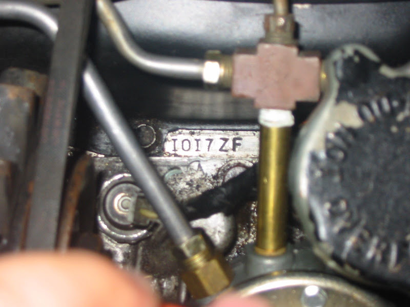
The second method added a fuel tank return line at the brass fuel pump outlet. This was added in 1968 and later engines when SMOG pumps and increasing engine compartment heat were introduced, along with a potential for vapor lock as stagnant, non-moving fuel quietly heated to a boiling point in the fuel lines while the mechanical fuel pump idled in a neutral condition caused by full float bowls (described above in the section The Corvair Fuel Pump Functional Operation.
The fuel return line is one of those unique features of the last few model years, along with the SMOG pump plumbing and other unique engineering features GM invented to satisfy the SMOG police, California Air Resources Board, etc.
The fuel return line "Z" shown below was added during the final few years of Corvair production. This fuel line runs from a "cross" 4-way connector at the fuel pump outlet. This small diameter fuel line is more restrictive than the lines routed to the carburetors. It permits a small but continual flow of gasoline to return to the fuel tank. Without it the fuel pump goes into NEUTRAL whenever the float bowls are full and the needle/seat valves are closed. This stops the flow of gasoline until the engine consumes enough gasoline to restore the fuel flow back into the float bowls again. By adding the fuel return line, some gasoline is constantly flowing through the fuel pump feed line from the fuel tank and then back again through the return line. Keeping a constant flow of fuel moving uses the cool liquid to cool the steel fuel feed line "D" to help prevent vapor lock.
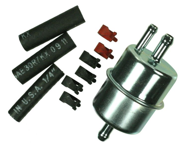
There are other brands and models of 3-port fuel filters, that include a fuel return line to the fuel tank...
3 port fuel filter
3 port fuel filter with 3/8" In Port - 3/8" Out Port - 1/4" By Pass and Vapor Port. Some Part Numbers to help you find one. This can be used with electric fuel pumps to keep the fuel cool in the engine compartment where temps can be 200 plus degrees.
Wix-33901 ACDelco-GF98 Powerflow-95041 Balwin-BF887 NAPA-3041 Hastings-GF20 Fram-G18 Motorcraft-FG12 Purolator-GF1118
These may need to be ordered as they are no longer a fast moving item in most stores. The 5/16" size is much more common.
Another option (instead of using a 3 port fuel pump) is a 3 port fuel filter after the pump. These were used on Large Engine GM Trucks, Ford Trucks and Jeep in their hot fuel packages. The small, or return port must be installed on top(or UP) so vapor is returned to the tank. Putting it on the bottom will trap vapor. Your Fuel Pump can handle this circulating flow very easy.
When you think about it, we really do not use very much fuel as we travel with our units. Therefore, there really is very little fuel flow through the fuel lines, basically stagnating and just sitting in the fuel line and pump. The fuel heats up at the pump and the lines leading to the pump near the engine. During this time, the fuel can vaporize and when it is in a gaseous state it simply pushes back and forth through the intake check valve of the fuel pump. The fuel pump cannot deliver sufficient fuel to the carburetor as required by the engine.
By keeping some fuel flowing through the fuel pump and low pressure fuel line, the temperature of the fuel pump, and fuel is significantly lowered and vaporization is avoided.
I believe either method could be adapted to any Corvair. A standard inlet/outlet 2-port filter could be substituted for the 3-port filter, but you would lose the vapor lock prevention feature. The 1968-1969 Corvair 4-way Tee brass fitting and an associated fuel tank return line could also be fitted, using parts like those shown on the Clark's Corvair Parts page. This would provide a more-positive, continuous fuel flow moving from the fuel tank and back again, which would create a liquid cooling system to keep the fuel lines feeding the pump cool.
Another fuel filter possibility for your consideration... Corvairs often sit for long periods of time. Water accumulation in the fuel can become a problem.
Pure ethanol is hygroscopic; it attracts water, to the point that it will pull it out of the air.
Ethanol and gasoline will mix, but ethanol, gasoline and water will not; the ethanol-water mixture
will come out of solution and settle on the bottom of your tank.
This type of fuel filter can be useful to keep the Ethanol-based fuel in your tank from feeding water to the "Waterless Wonder from Willow Run".
FST Performance wrote:How often do I need to change the filter? (this is our #1 asked question)
This depends; how dirty is your fuel? You may be able to run several months on a spin-on/filter, then all of a sudden, it plugs up due to one batch of dirty fuel. This even happens with race fuels that have sat in tanks too long and collected water.
We recommend to change the fuel filter any time that you change your oil filter. Or, to get some type of time frame; every time you change the oil filter, remove the FST fuel filter and drain it into some type of clear container and let the fuel set; after a short time, look to see if there is any water (it will separate from the fuel)...if the "fuel" looks clear, then put a film of oil or grease on the filter seal and put it back on...if the fuel looks cloudy, change the filter.
https://www.amazon.com/s/ref=nb_sb_noss ... tor+filter
There are many different designs, price ranges, filtration quality, etc. Do your homework on filter life, water drain capability, etc. Sounds like a good idea... especially with water separation capability from stale fuel and water absorbing modern gasolines.
Brad Bodie Lake Chatuge, North Carolina 1966 Corvair Corsa Convertible
Thanks for the pictures! Interesting that it is just a hole. I was thinking maybe it had some kind of spring valve to act somewhat like a pressure regulator. Now we know.
157 Corvairs, 5 Ultravans and counting
Northlake, TX
joelsplace wrote: ↑Sun Apr 21, 2019 8:25 pm Interesting that it is just a hole. I was thinking maybe it had some kind of spring valve to act somewhat like a pressure regulator. Now we know.
Similar to what the A.I.R. engines did for their fuel return system. It is just a small orifice in the T of the pump discharge.
joelsplace wrote:Thanks for the pictures! Interesting that it is just a hole. I was thinking maybe it had some kind of spring valve to act somewhat like a pressure regulator. Now we know.
I was surprised also but even more so that it didn't filter it first. If a large enough piece of rust or junk plugged it up that would be the end of the return flow.
joelsplace wrote: ↑Sun Apr 21, 2019 8:25 pm Interesting that it is just a hole. I was thinking maybe it had some kind of spring valve to act somewhat like a pressure regulator. Now we know.
Similar to what the A.I.R. engines did for their fuel return system. It is just a small orifice in the T of the pump discharge.
Thanks for the pictures! Interesting that it is just a hole. I was thinking maybe it had some kind of spring valve to act somewhat like a pressure regulator. Now we know.
I believe they would call that fuel passageway in the filter a "metered orifice" — just like the restrictive hole in the 1964 and later PCV system. It is just a calibrated leak to return fuel to the tank and keep things flowing and cool.
Brad Bodie Lake Chatuge, North Carolina 1966 Corvair Corsa Convertible


 1966 Corvair Corsa Convertible