joelsplace wrote:...Since you are big on how they were engineered and don't care about real world experience would you please explain why the original instructions said to use the resistance wire? Do you think the engineers redesigned the Pertronix 1 at the same time they changed the instructions? Also why do they come with the right length wires and ring terminals to connect directly to the coil?
I've also been told by other Corvair mechanics that all the burned out ones they have replaced have been wired to 12v. To be fair I have read about one mechanic that said he's fixed poorly running Pertronix 1 installations by switching them to 12v but that is only one. If I ever have an issue with any of my Pertronix 1 cars I'll try switching it to 12v but so far no issues.
I have a Pertronix Ignitor in my 1966 Corvair Monza Sedan, and i am quite happy with it. I also have 24 years of experience in the Air Force as an electronics technician, and retired as an E7 (Master Sergeant). So I do have some understanding of the technical aspects of electronic systems and components. I have been around Corvairs since I was 8 years old, took my first driver's test in a 1965 Corsa convertible in 1969, and have continued to drive and maintain my Corvairs throughout my Air Force career while supporting and raising my family at locations throughout the USA and in Europe. At age 70 I still drive Corvairs as "daily drivers" and write on the Corvair Forum to try to contribute — where I have some experience — to try to assist other Corvair owners where I feel I can.
I have been trying to explain why an upgrade to an electronic ignition system is generally a wise choice as it reduces maintenance problems and increases reliability while driving these aging cars. I have installed optical trigger (Crane Cams/FAST) and magnetic trigger ignition systems in my Corvairs, and have never regretted it. I do carefully read the sometimes confusing or poorly written instruction manuals, and as such realize where many of the pitfalls and problem areas are, and why these electronic ignition systems can malfunction or cause problems — especially if the installation instructions are not understood, properly interpreted, or followed.
In the Air Force our electronic maintenance instruction manuals are called Technical Orders. We maintain and repair millions of dollars worth of electronic systems throughout the world, and many of these systems support high priority, critically important communications systems that must be maintained and operated for maximum reliability. As a supervisor I was trained to insist that all work be done while referencing the applicable Tech Orders, and we train our enlisted technicians to understand and adhere to the written procedures contained in USAF Technical Orders, and other Air Force regulations, manuals and Defense Communications Agency reference materials.
Military Tech Orders, whether applicable to electronic systems, aircraft, cars and trucks, or whatever is being maintained and worked on are routinely upgraded and revised — and changes to those Tech Order libraries are received and posted all the time. There can be many reasons for revisions and changes to existing published Tech Orders, but we are required to update and maintain the Tech Orders that are applicable to our systems and post those revisions as soon as possible after the changes are received. The reasons for the changes are often procedure clarification or error corrections — but the intent is to acknowledge the need for improved documentation to ensure that proper maintenance procedures are readily available in the field.
So what makes you think that a Pertronix instruction manual is not subject to being revised, improved upon, or rewritten over time? Most companies have a technical support/customer support unit that answers requests from customers for guidance or clarification. Frequent questions or confusion on the part of customers may often result in a modification to published instruction manuals to make them easier to understand or to reduce confusion. The components sold by Pertronix may also be revised or improved over the years, if technical flaws are noted.
I have been attempting here to point out why installing a Pertronix Ignitor in accordance with an original, or old instruction manual may be a mistake — ESPECIALLY IF PERTRONIX PUBLISHED A REVISED MANUAL TO CLARIFY A PROBLEM AREA, SUCH AS A FREQUENT ISSUE WITH LOW-VOLTAGE RESULTING IN A MALFUNCTION OR IN UNSTABLE OPERATION. If an early instruction manual did not state that the ballast resistor should be bypassed, and it was later determined that leaving a ballast resistor in the Primary circuit could cause problems, Pertronix would likely revise the instructions based on customer feedback and frequent complaints received by Customer Service. As written in the Pertronix Australia online help website I referenced earlier...
PERTRONIX wrote:PERTRONIX IGNITOR AND COIL INSTALLATION TROUBLESHOOTING
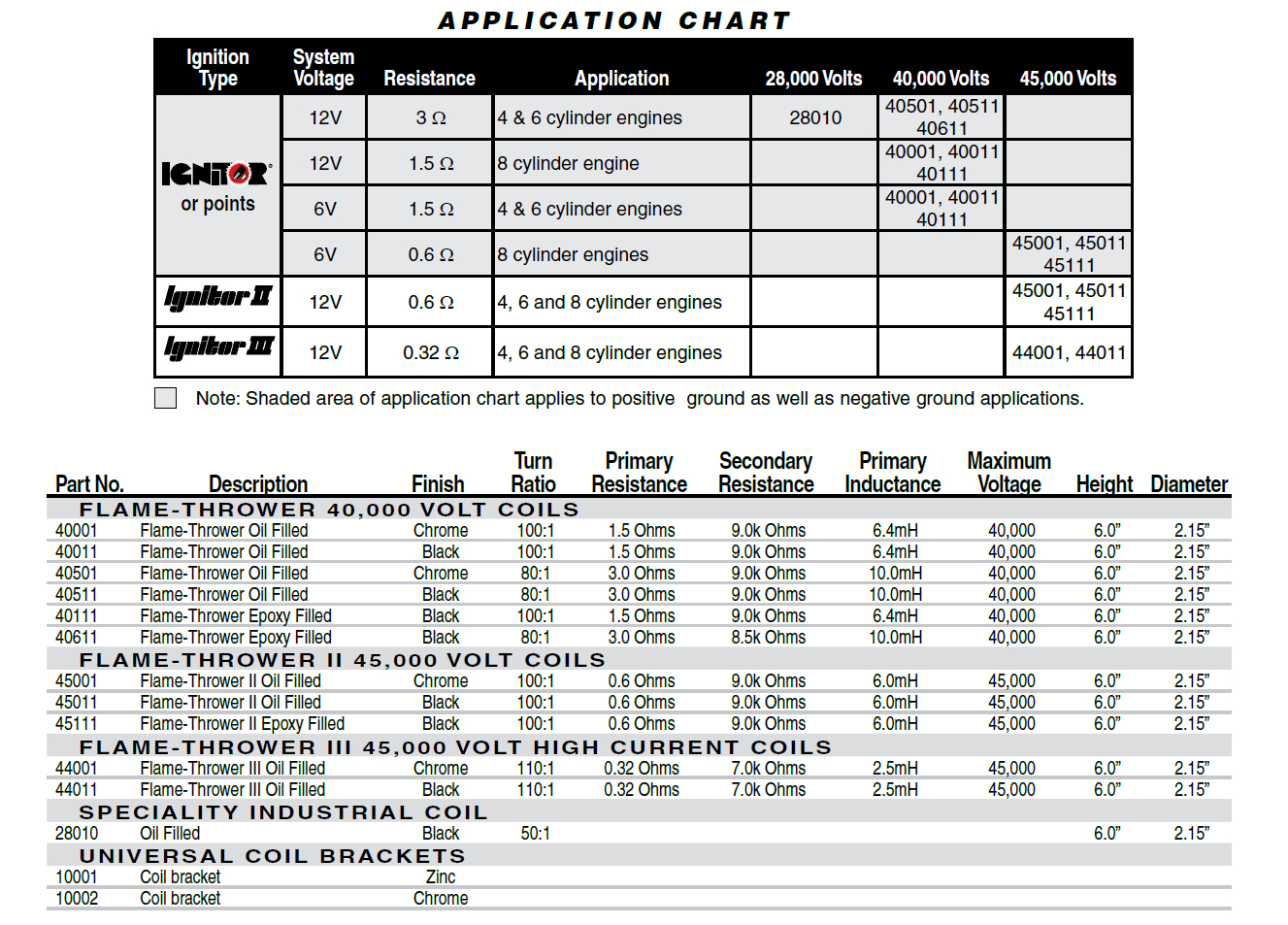
WHAT APPLICATIONS ARE COVERED WITH THE PERTRONIX FLAME-THROWER COILS?
Our Flame-Thrower coils are designed specifically for compatibility with our Ignitor 1, 2 and 3 units. However, the Flame-Thrower 1 Coil may also be used with a point type system or any other system that calls for a 1.5 or 3.0-ohm coil.
MY VEHICLE IS MISFIRING OR BREAKING DOWN UNDER LOAD. WHAT SHOULD I DO?
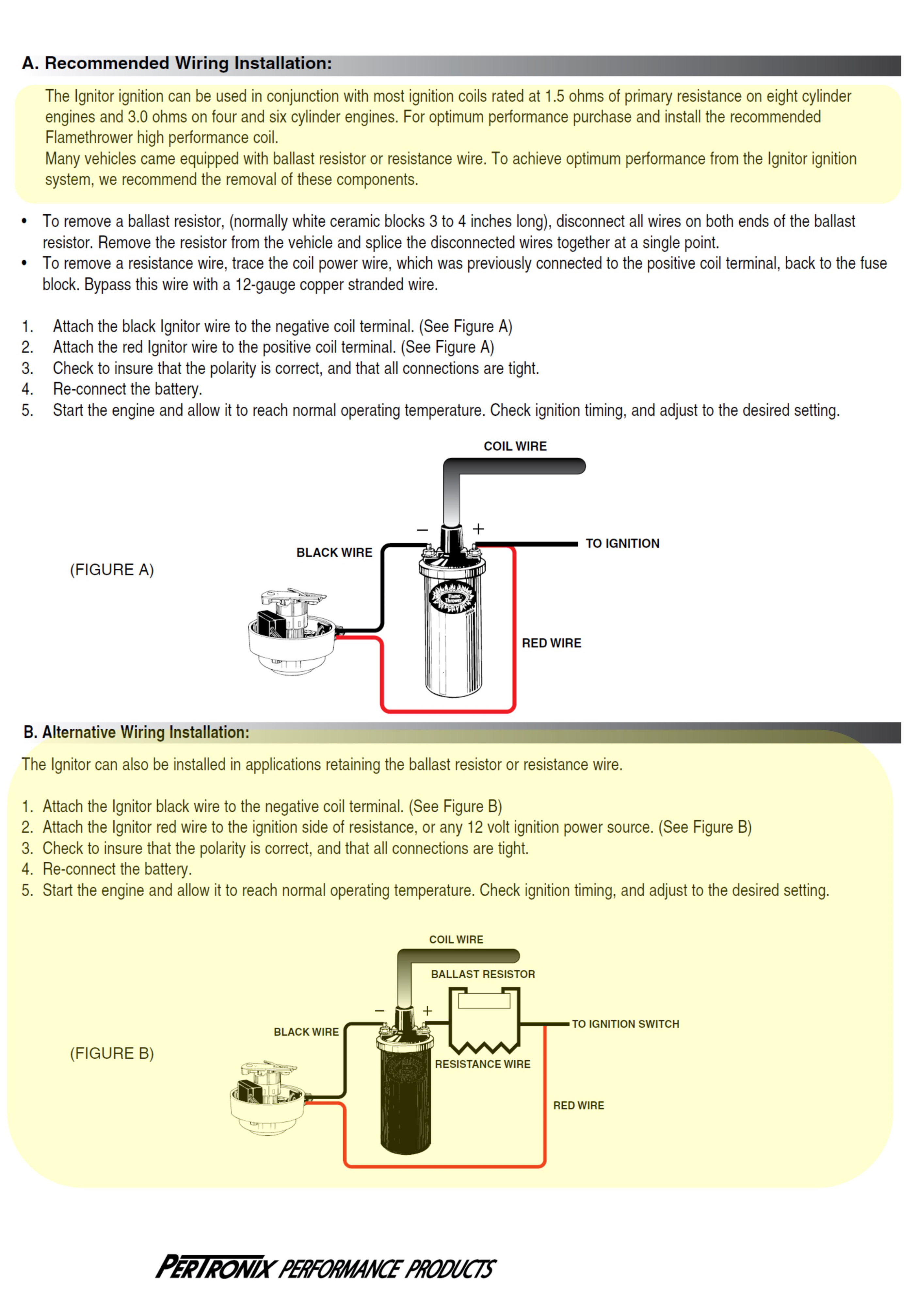
This problem is NEARLY ALWAYS associated with low voltage at the unit, preventing the unit from operating correctly. The unit is actually turning off, and back on as the coil charges and releases energy. The best possible remedy for this problem is to wire the Ignitor unit's RED WIRE directly to a switched 12-volt source away from any voltage reduced circuit, such as a resistor wire or ballast resistor. These circuits usually are in the wire from the ignition switch to the coil. The Ignitor™ lead (red wire) can go directly to the ignition switch or any other "switched" source on the fuse panel. The coil will still need a minimum of 1.5 ohms of resistance, either internally such as the Flame-Thrower or in the form of a resistor wire or ballast resistor. We think you will find when you have these "breaking up" problems, low voltage is the culprit!
We also highly recommend seeking a qualified auto-electrician to make this adjustment for you.
The online help goes on to describe how to resolve such problems. Pertronix has also revised their instruction booklets to instruct installers how to test for the presence of a ballast resistor or resistor wire, and how and why it should be bypassed.
I have read comments from others stating that they installed a Pertronix Ignitor while leaving the ballast resistor in the circuit. They even stated that the original manual from Pertronix said that it was OK to do that! They effectively called Pertronix "stupid" for later revising their instruction booklet, which now indicates that the ballast resistor should be bypassed. I tried to show why this would make sense, since the original circuit that supported ignition points used a voltage divider circuit that routinely causes the voltage to drop down too far for proper Pertronix Ignitor function. Their instructions indicates that the ballast resistor should be bypassed for the Pertronix Ignitor. The Pertronix instructions further indicate that the ballast resistor may be retained for the original 1.5 ohm coil ONLY, to help the coil by reducing heat buildup in the 1.5 ohm coil. Alternately, Pertronix recommends switching to a 3.0 ohm coil (with a 4 or 6 cylinder engine) that is engineered to be powered directly by the nominal 12 VDC vehicle power source. Either way, the Pertronix Ignitor gets full system voltage within the specified range of 8-16 VDC, while the coil has approximately 3 ohms of resistance (by retaining the 1.8 ohm ballast resistor plus the 1.5 ohm coil, or by switching to a 3.0 ohm coil) to limit internal Primary current and heat buildup within the coil.
So why defend the original ballast resistor voltage divider setup that was designed in the 1960s and earlier to support ignition points? THE MODIFICATION AND CHANGE TO A PERTRONIX IGNITOR ELECTRONIC IGNITION SYSTEM DEMANDS THE REMOVAL OF THE BALLAST RESISTOR TO ENSURE PROPER SOURCE VOLTAGE FOR THE PERTRONIX IGNITOR! The points and condenser, which was the main reason for the ballast resistor in the first place, have been removed from the vehicle! Retaining the ballast resistor in the Pertronix Ignitor power circuit places the Ignitor operating at or below the bottom-end of the acceptable range of 8-16 VDC. Some may get away with it, and others may have problems surface — as described in the Pertronix troubleshooting guidelines.
Pertronix has revised their published instructions and provided technical support via telephone or via Internet online troubleshooting guidelines to try to clarify instructions for a proper, trouble-free installation. Those who choose to ignore those revised instructions may choose to do so, since they know better than the stupid Pertronix engineering and customer support team!
I believe that I understand the reason for the revised instructions from Pertronix. They have stated that their Pertronix Ignitor will function properly if the input voltage never dips below 8 VDC and never exceeds 16 VDC. It must also have a proper ground, and Pertronix' instructions explain how to test and evaluate the source voltage and the system ground. I've shown how the voltage divider may cause the source voltage to dip below 8 VDC, and how an improperly operating alternator or generator voltage regulator can sometimes cause the charging system voltage to rise above 16 VDC. I even recommended adding a voltmeter to the Corvair instrumentation, which will tell you a lot more than the factory "IDIOT LIGHT". A poor ground for the Pertronix Ignitor can also cause a malfunction. All of this is discussed in the newest Pertronix installation instructions.
I will continue to encourage Corvair owners to upgrade their ignition systems to eliminate the points and condenser. I also encourage moving the coil away from the hot cylinder head and mounting the oil-filled coil vertically to avoid leaks, retaining the Delco 1.42 ohm coil coupled with an external ballast resistor wire in the circuit (the original Corvair configuration), or alternately removing/bypassing the ballast resistor wire altogether and substituting an aftermarket 3.0 ohm coil. The Pertronix Ignitor II can work OK in the Corvair, with the exception of the slow-idling Powerglide Corvair, and the Flamethrower II 0.6 ohm coil is simply overkill and not needed in the Corvair, and is more costly and potential trouble that should be avoided.
I care very much about real world experience, and when there appears to be a discrepancy between the experience others have had and the recommendations/guidance/published instructions provided by the equipment manufacturer (in this case, Pertronix) I try to determine the reason. In this case, it appears that those who power the Pertronix Ignitor by tapping off of the positive ignition coil terminal (as shown in the Pertronix instructions), but also disregard the advice to bypass the ballast resistor in the vehicle Primary ignition circuit will typically power the Ignitor module with only about 6.17 VDC (assuming 14 VDC from the alternator or generator). When starting the engine, the starter solenoid bypasses the voltage divider circuit, powering the Ignitor with full battery voltage of approximately 12 VDC. This, of course, meets the Pertronix standard for the Ignitor of between 8 and 16 VDC, but the moment the engine starts and the key is released, the voltage to the Ignitor drops back to about 6.17 VDC because of the ballast resistor wire. While this is significantly lower than the 8 VDC minimum specified by Pertronix, it appears that it is often just enough to keep the engine running. Any further power degradation, however, might just be enough to introduce unstable operation. Variables such as a poor ground or a discharged or weak battery output might be enough to introduce faulty operation of the Pertronix Ignitor module. These variables and differences from car to car might explain why some owners have problems, while other say that it is OK to leave the ballast resistor wire in the circuit.
Removing the ballast resistor wire from the circuit places the voltage to the coil positive terminal consistently at the typical 14 VDC seen with an engine running and the charging system in operation, since the voltage divider circuit no longer exists with the ballast resistor wire removed. But in this configuration, the stock Delco-Remy 1.42 ohm ignition coil is also powered continuously at full system voltage, which could cause the coil to run hot. This could be remedied by either replacing the coil with a 3.0 ohm coil (substituting a coil that is engineered to run with a full charging system output powering it), or by powering the original Delco-Remy coil using the stock Corvair voltage divider/ballast resistor wire circuit, but powering the Pertronix Ignitor separately by attaching a power wire for the Pertronix Ignitor directly to the Corvair wiring harness, BEFORE the ballast resistor wire.
NOTE: BOTH of the above ignition coil options are outlined in the Pertronix instructions shown below.


 1966 Corvair Corsa Convertible


 [/img]are-Clinic_ATBGO_Brand-Mark_Red-2.png[/img]