I was too rushed and failed to read everything carefully...
Blair wrote:I cant see any words on the fuse box so I looked around the internet for a picture of the same one with no luck. Could someone on here could provide me with one? The yellow wire that is connected to the fuse box goes to the electric fuel pump. This is the only thing keeping me from taking it on the road. The tail lights also are not working and neither are the reverse lights. But that's the least of my concern. After all the work I've done to it I just don't want to get rear ended. I need brake lights
It appears that the fuse you should be concerned with is the second fuse up from the flasher, labeled TAIL/STOP DOME. This fuse provides power to the dome light and to the light switch (control of the taillights), and to the brake light switch at the brake pedal. The power wire that feeds all of this is labeled 16 B/OR (16gauge Black/Orange stripe). The power feed for the circuit is not switched, so all devices on the circuit have access to continuous battery power and are not controlled by the ignition switch position. If you have access to a multimeter, check for voltage at the input terminal on the brake light switch. (Ground the black wire on the multimeter and touch the red wire to the voltage input connector at the stop light switch — multimeter set to measure 12 V DC). If you can measure voltage going into the stop light switch at the brake pedal, and coming out of the stop light switch when you press the brake pedal, you know that your power source and fuse are good. The third fuse up provides power for the backup lights and heater.
Left-click the image to enlarge it for better viewing...
 Viewed 1784 times")
- 1964 Fuse Block and Fuse List
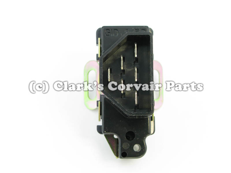
Another "common thread" to the taillights, brake lights, turn signal lights, and backup lights is the ten pin multi-connector in the engine compartment (on the left side, below the voltage regulator). This plastic shell encases 10 metal connectors that should make positive electrical contact when the two halves of the shell are fully seated. However, this connector is often more than 50 years old and is subject to years of vibration, moisture, and heat which can promote corrosion and poor electrical contact between the two halves. This could be a point of interruption for all of the taillights in the car. Again, using a multimeter, you can separate the two halves and follow the wire color codes to identify the terminals of interest on the firewall side of the connector. You should be able to measure voltage at the terminals that are responsible for taillights, brake lights, backup lights, etc. when the necessary switches are on. You should also examine the physical condition of the metal terminals to see if they are bent, damaged, or corroded. Sometimes simply unplugging the two halves and then re-seating them is enough to reestablish electrical continuity. But when the two halves are separated try to carefully examine all of the metal connectors to see if you can see any signs of burning or corrosion or connectors that are bent and may not be making contact with the other half.
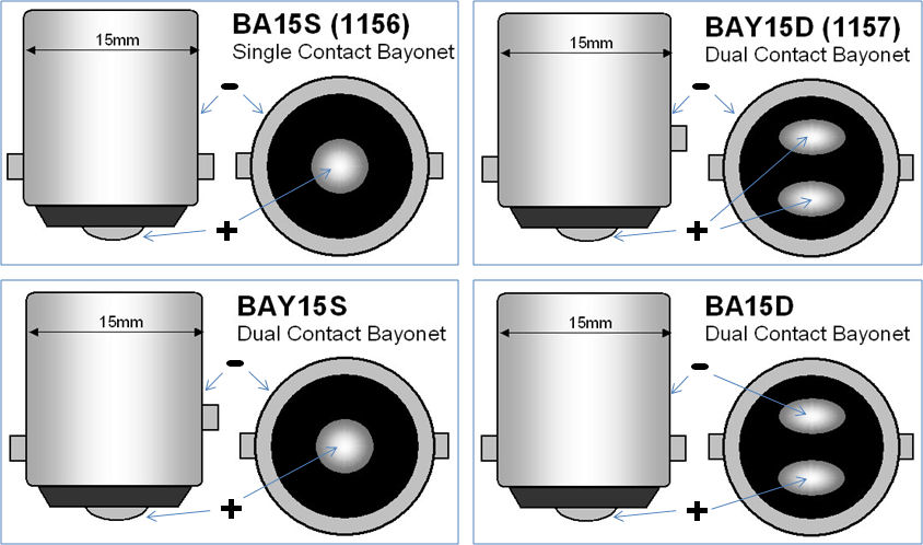
Finally, check that each bulb housing is providing a good chassis ground return for each bulb socket. Also make sure that each bulb is the proper two terminal 1157 dual filament bulb, and that the guide/locking pins are properly positioned and seated. (You can confirm that each bulb socket is grounded by setting your multimeter to measure electrical continuity (ohms). Touch one test probe to the socket housing and the other to battery ground.
Each side of the car rear uses an 1157 bulb (also used in the trunk), which has two contacts and two filaments. Ground return for both filaments is the bayonet base/lamp socket. Each 1157 bulb only requires TWO WIRES — one for the tail lamp, and the other for the brighter (dual purpose) turn signal/brake filament.


1156 bulbs only belong in the backup light sockets. The two locking pins n the 1157 bulb are positioned at different heights on the side of the bayonet base/lamp socket, to ensure that they are properly inserted.
I have also attached appropriate sections of the 1961 Corvair Shop Manual and the 1964 supplement…