
My analysis...
1. A single wire feeds the fan motor DC Voltage. Ground return is via the motor case to chassis ground.
2. Two resistors of different values in the resistor pack reduce power to the motor, to provide two lower speeds.
3. The fan switch sends power to the fan motor either directly, or diverts power through the resistor pack in the trunk... through Resistor 1 only, or through both resistors in parallel. The reduced power then returns from the resistor pack to power the fan motor at the selected lower speed.
The first diagram below is an attempt to show the basic heater fan wiring, while eliminating the remaining Corvair wiring from view. The
BROWN wire is the power source from the fuse block (battery). The BLACK/
ORANGE wire is the main supply line to the motor. The
DK. GREEN wire is simply a voltage tap to feed the backup light switch. It has no relationship with the fan circuit.
Moving the fan switch from OFF to HIGH establishes a direct connection from the power source (FUSE BLOCK) to the FAN. No resistors or trunk wiring are in the circuit. The two reduced fan speeds are obtained by bypassing the direct connection to the fan motor, and routing the power to the resistor pack in the trunk. The Fan Switch selects a circuit to pass current through either Resistor 1 only (LOW SPEED) or Resistor 1 plus Resistor 2 (MEDIUM SPEED). Power passes through the selected resistor(s) and then returns back to the fan motor via the BLACK/
ORANGE wire, and the motor operates at a reduced speed, as determined by the current limited through the selected resistor value.
 Viewed 1694 times")
- Late Model Heater Control
 Viewed 1694 times")
- Corvair Trunk Resistor Module
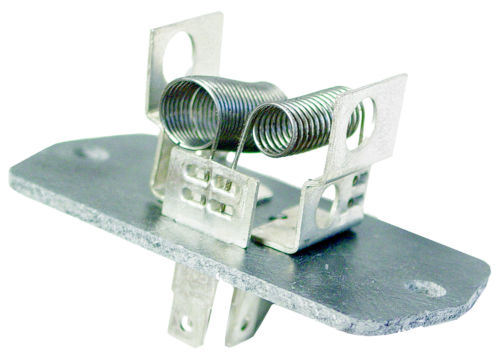
- Heator Resistor (4).JPG (25.17 KiB) Viewed 1688 times
This schematic shows the entire 1965 Corvair wiring diagram...
Left-click on the diagram with your mouse to enlarge for improved viewing...
 Viewed 1694 times")
- 1965 Corvair Schematic Diagram
Wire color codes in EM Corvairs may vary with the model year, but the principles of operation remain the same for all model years.


 1966 Corvair Corsa Convertible
 Connecting "B" (Battery Power) to resistor "L" (Low Speed) or to "L" plus "M" (power through BOTH resistors to produce Medium Speed) is not confusing. But moving the switch all the way to apply power to both "M" and "H" might seem to be confusing, unless you realize that a direct connection between "B" and "H" is a direct short from the battery power to the motor "H", which effectively bypasses the resistor "M". The fact that the contact is still touching "M" is irrelevant, since power is applied directly to the motor input and the resistor "M" has no impact on the circuit.