I am working on wiring the engine bay and I have a couple of questions on where these wires go. The diagrams aren't super clear and I never had a reference as mine was in pieces when I got the car.
For the generator, are those wires correct? Blue on the terminal on the right and brown on the left?
For the coil, which terminal do both the brown and the striped green end up on? I thought I found a diagram that showed brown on the positive, but I am still not sure.
Finally, I have a turbo so I have the fuel return. Which grommet does the fuel return run through? I think it is the double hole grommet with the wire harness, but my old one had the manifold vacuum line running through that instead.
Which leads me to which grommet does the vacuum line run through if not the double grommet? I have a diagram from Clarks with the 4 hole grommet and it is not mentioned there.
Couple of Qs on wiring and fuel lines
-
arctic_man
- Posts: 7
- Joined: Sun Aug 07, 2022 1:04 pm
-
bbodie52

- Corvair of the Month

- Posts: 11945
- Joined: Mon Aug 06, 2012 12:33 pm
- Location: Lake Chatuge Hayesville, NC
- Contact:
Re: Couple of Qs on wiring and fuel lines
Left-click the image to enlarge it for better viewing. Click a second time for maximum enlargement...
- 1964 Corvair Passenger Car Combined Schematic
According to the shop manual schematic diagrams, the DARK BLUE wire connects from the voltage regulator FIELD terminal to the generator FIELD terminal on the left side, and the armature wire (BROWN) connects to the generator terminal on the right side. YOU APPEAR TO HAVE THESE WIRES REVERSED!
(SEE PAGES ENGINE ELECTRICAL 8-4 - 8-5 in the 1961 Corvair Shop Manual)
- 1964 Corvair Generator Charging Circuit
bbodie52 wrote:I have attached a copy of the 1961 Chevrolet Corvair Shop Manual - Section 8 - Electrical Systems to guide you through some basic tests to ensure that the charging system voltage output is not excessively high. When you reconnect a new battery to the system, a generator-based system should be polarized, as outlined in the shop manual.
Generator-based charging systems mandate a procedure for POLARIZING the charging system. This should be done whenever the battery has been disconnected...Why do generators need to be polarized? Generators need some magnetism to get started. This "residual" magnetism remains in the field pole pieces even after the engine has stopped. The next time the generator starts up, the residual magnetism creates a small voltage in the Armature windings. Not enough to charge the battery, but enough to allow the field windings to draw current. As the field current increases, the pole pieces create even more magnetism. That makes even more voltage in the armature, and the cycle continues until the generator is capable of producing maximum output.
Anytime a generator is disconnected from the system, there is a possibility the residual magnetism may have decreased to the point where it can no longer get the generator started producing voltage. In the case of a new generator or one which has been mis-treated, the residual may even be of the wrong direction (north and south poles reversed).
Polarization is a simple process used to restore the field pole residual magnetism and ensure the magnetic direction is correct.
Polarization is a procedure which matches the polarity for the generator and the voltage regulator. The majority of the vehicles are manufactured negative ground although some of the older vehicles were manufactured positive ground. The generator has to be set up for either polarity. The generator will charge either way, however the voltage regulator has only one polarity. Whenever the battery is disconnected from the vehicle for any reason the polarization procedure should be performed.
The recommendation on how to polarize a charging system is the following: After the installation of a battery, generator or voltage regulator follow these procedures. The terminals on the voltage regulator are labeled with letters and this is where you will do the polarizing procedure. Both of the components will have battery power so do not start the vehicle or turn on the ignition switch before polarizing them. You will need a small piece of wire fourteen or sixteen gauge with alligator clips on the ends. Find the “B” terminal on the regulator and attach one of the alligator clips, find the “D” terminal and touch the terminal with the other alligator clip. You can touch the terminals a few times and it will produce a soft light spark. Under no circumstances touch the “F” terminal or any other part of the regulator or you could damage the regulator.
bbodie52 wrote:If you have a generator-based charging system, this information applies...
CHARGING SYSTEM (GENERATOR TYPE ONLY)
Whenever the battery is disconnected from the vehicle for any reason the polarization procedure should be performed.
The recommendation on how to polarize a charging system is the following: After the installation of a battery, generator or voltage regulator follow these procedures. The terminals on the voltage regulator are labeled with letters and this is where you will do the polarizing procedure. Both of the components will have battery power so do not start the vehicle or turn on the ignition switch before polarizing them. You will need a small piece of wire fourteen or sixteen gauge with alligator clips on the ends. Find the "Batt" terminal on the regulator and attach one of the alligator clips, find the "Armature" terminal and touch the terminal with the other alligator clip. You can touch the terminals a few times and it will produce a soft light spark.
Under no circumstances touch the "Field" terminal or any other part of the regulator or you could damage the regulator.
http://www.vv.corvair.org/pipermail/vir ... 13475.html
What you want to do is polarize the generator. If in fact it ran with reverse polarity, everything should be fine after this process. You should not have damaged anything yet.
With key off, use a piece of 14 guage or larger wire to jump between the battery and armature terminals of the voltage regulator. I am at work without a shop manual, so I forget the actual writing on the terminals. BUT, it is the top and middle terminal on Corvairs (with the regulator mounted stock position, red wires on top terminal).
It will spark! Hold for 1 or 2 seconds. The wire may also get warm, be prepared.
Start engine again and check for red light going out.
IT IS IMPORTANT TO POLARIZE A NEW GENERATOR BY FOLLOWING THE PROCEDURES IN THE CORVAIR SHOP MANUAL. THIS PROCEDURE IS DESCRIBED ON PAGE 8-18 OF THE ATTACHED SHOP MANUAL SECTION. This polarizing procedure applies ONLY to vehicles equipped with a GENERATOR. It does not apply to vehicles equipped with an alternator.
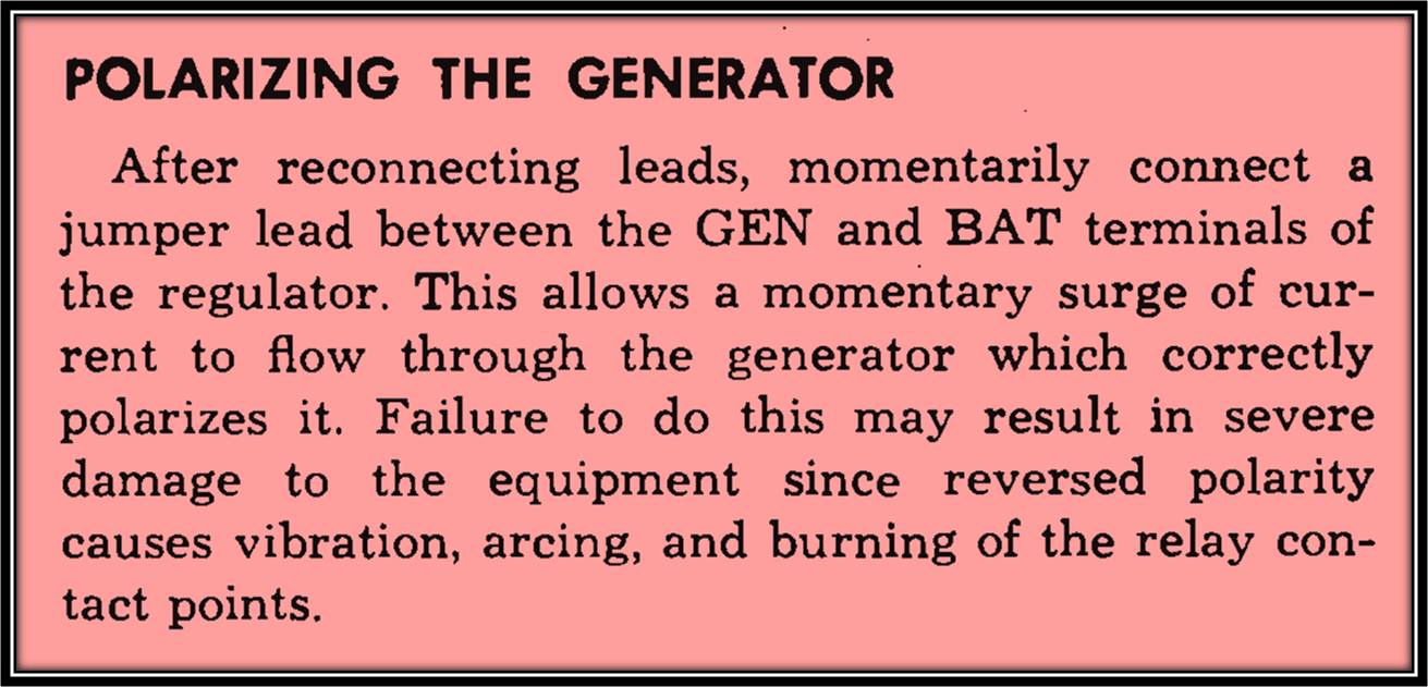 ... Gospel According to General Motors, 1961 Chevrolet Corvair Passenger and Commercial Vehicle Shop Manual, ENGINE ELECTRICAL, Page 8-18
Since you had a battery exploded, it would be reasonable to assume that the battery had been producing excessive gas that can be explosive if it accumulates. Low battery water is a sign that overcharging has been occurring, but at this point the old battery is not capable of showing this kind of evidence!
In any case, after installing a fresh battery and polarizing the generator system, it might be a good idea to use a voltmeter to check the charging voltage. The battery itself produces approximately 12.5 VDC, and a properly adjusted and regulated charging system, with the engine revved to approximately 1500 RPM or so, should not exceed 14.7 VDC. If you find that you have excessively high charging voltage, the tests and adjustments outlined in the manual should be performed, and/or the voltage regulator should be replaced. Operating the system for long periods with a high charging voltage could produce a gas buildup, which may be the cause of your original explosion.
REFERENCE...
CORVAIR COMBINED WIRING SCHEMATIC DIAGRAMS
- Attachments
-
- 1961 Chevrolet Corvair Shop Manual - Section 8 - Electrical Systems.pdf
- 1961 Chevrolet Corvair Shop Manual - Section 8 - Electrical Systems
- (3.28 MiB) Downloaded 9 times
-
- 1964 Supplement - Chevrolet Corvair Shop Manual - Section 8 - Electrical Systems.pdf
- 1964 Supplement - Chevrolet Corvair Shop Manual - Section 8 - Electrical Systems
- (1.95 MiB) Downloaded 8 times
Brad Bodie
Lake Chatuge, North Carolina
 1966 Corvair Corsa Convertible
Lake Chatuge, North Carolina
1966 Corvair Corsa ConvertibleRe: Couple of Qs on wiring and fuel lines
Brad has covered the generator/regulator wiring very well.
Your picture of the coil is an issue. The 1964 Spyder was the first Spyder model year to drop the ceramic ballast and go with the in harness ballast wire, same as the Monza. The BLACK/YELLOW wire is the ONLY wire that should go to the coil "+" terminal. The BLACK wire should be from the distributor points (or electronic module) and connect the the coil "-" terminal. What looks like a light purple should be a BROWN wire (could be picture color is off) that goes to the tachometer and connects to the coil "-" terminal.
Your coil is obviously NOT original and that could be an issue. The coil resistance across the primary side (between terminals "+" and "-" with NO wires hooked up) should be 1.3 to 1.5 ohms. Less or more and you will have ignition problems.
Good luck.
-
Frank DuVal

- Posts: 476
- Joined: Wed Dec 09, 2009 4:58 pm
Re: Couple of Qs on wiring and fuel lines
Generator. Look carefully, there is an A and an F embossed. Armature and Field. Big wire (diameter) goes on A smaller wire goes on F. Current out of A is much larger than current going into F. 
Hot wire (measure with voltmeter if not sure, key on, wires off the coil) goes on coil +, tach wire and wire into distributor goes on -.


Hot wire (measure with voltmeter if not sure, key on, wires off the coil) goes on coil +, tach wire and wire into distributor goes on -.
Frank DuVal
Fredericksburg, VA
Hey look, blue background!


Fredericksburg, VA
Hey look, blue background!


-
bbodie52
- Corvair of the Month
- Posts: 11945
- Joined: Mon Aug 06, 2012 12:33 pm
- Location: Lake Chatuge Hayesville, NC
- Contact:
Re: Couple of Qs on wiring and fuel lines
The POWER wire on the coil POSITIVE (+) terminal provides voltage from the ignition switch at the instrument panel when it is in the ON position. This voltage is reduced from the battery voltage (NOMINAL 12.5 VDC) by a 1.8 Ohm ballast resistor wire, which is embedded in the Corvair wiring harness. IN SOME CORVAIR SPYDER MODEL YEARS, GM USED A SEPARATE BALLAST RESISTOR TO REDUCE THE VOLTAGE FED TO THE IGNITION COIL.
The Black wire with the Yellow stripe is the power lead that connects to the coil POSITIVE terminal. The condenser on the side of the coil also connects to the coil positive terminal, for AM Radio static noise suppression.
The Black wire lead from the ignition coil connects to the ignition points (inside the distributor). The DISTRIBUTOR POINTS are a simple on/off switch that provides a GROUND connection to the coil NEGATIVE terminal when the points contacts are closed by the distributor six-lobe cam. This action turns the ignition coil on and off — causing a properly timed high voltage spark plug voltage to be discharged through the distributor cap to the appropriate individual spark plug each time the points open.
Since your Corvair Spyder has a a tachometer, there is an extra (BROWN) wire in the engine compartment that connects the tachometer to the ignition coil NEGATIVE terminal. This is a tachometer sensor wire that provides a signal to the tachometer each time the points open and close. The tachometer is calibrated for a six-cylinder engine, so that these ignition pulses can be counted and translated into an engine RPM speed indication by the tachometer.
This tachometer connection is shown in the engine compartment wiring schematic provided in the attached 1964 Corvair Shop Manual Supplement.
The ONLY thing that that outside condenser is used for is to prevent radio interference from the ignition system. Without it you may hear popping or static that speeds up or slows down with your engine speed! It is part of the Radio Static Suppression system...This system is comprised of the following: Resistor Spark Plugs,Resistor Ignition cables (Carbon coated fiberglass core) ,condenser on voltage regulator(to prevent popping static) ,condenser on alternator(to prevent a high ptched whine, and in some special cases like older Corvettes... Ignition Shielding(metal shields on Distributor,plug wires,coil etc.) Also braided ground straps found on engine and other items under the hood!!!
This Suppression Condenser acts like a shock absorber + storage device that sends stray voltage harmlessly to ground!!!
On a - negative ground system always connect this condenser to the HOT + Positive side of any electrical item. (On + positive ground systems connect to - Neg. Hot side).
This Suppression Condenser is NOT THE SAME as the one inside the distributor which stores voltage from coil+ helps voltage field to collapse and fire the coil's high voltage secondary side. While doing this it also prevents the ignition points from excessive wear+burning+welding together!!!
I hope this better clears up your question?
Brad Bodie
Lake Chatuge, North Carolina
1966 Corvair Corsa Convertible
Lake Chatuge, North Carolina
1966 Corvair Corsa Convertible-
arctic_man
- Posts: 7
- Joined: Sun Aug 07, 2022 1:04 pm
Re: Couple of Qs on wiring and fuel lines
Sweet. Thanks for the wealth of info. I saw on the diagram some letters for the generator but either did not look hard enough or they are not on mine. I will swap those out and do some testing.
The harness is from Clarks. My old one had a bunch of missing ends so I am unsure if my old harness had the tach wire. But good to know it goes to ground. I need to pop a terminal on the end of the black and connect that to the negative. I will also check the resistance before I get too much further. The one that was attached was pretty well spent, so I swapped this with a Standard Motor Products brand.
The harness is from Clarks. My old one had a bunch of missing ends so I am unsure if my old harness had the tach wire. But good to know it goes to ground. I need to pop a terminal on the end of the black and connect that to the negative. I will also check the resistance before I get too much further. The one that was attached was pretty well spent, so I swapped this with a Standard Motor Products brand.
64 Spyder
04 XJR
04 SRX
05 Grand Cherokee Limited
04 XJR
04 SRX
05 Grand Cherokee Limited
-
joelsplace
- Posts: 2041
- Joined: Wed Oct 13, 2010 12:51 pm
- Location: Northlake, TX
Re: Couple of Qs on wiring and fuel lines
The negative terminal on the coil is grounded intermittently by the points to make a spark. If you ground it to chassis ground you won't have a spark.
157 Corvairs, 5 Ultravans and counting
Northlake, TX
Northlake, TX
Re: Couple of Qs on wiring and fuel lines
I assume you mean a "Standard Motor Products" brand coil. A lot of different coils. Today the coil that is listed for a 1965 Chevy Impala 283c.i. V8 engine is as close as you will come to what was in the Corvair. There are aftermarket coils, but many are all hype and NO GO. That said a "turbo" engine requires a good ignition during high boost. Today many do ignition upgrades for Turbo engines. AVOID the Pertronix coils, I've had too many issues.arctic_man wrote: ↑Wed Apr 03, 2024 9:30 am Sweet. Thanks for the wealth of info. I saw on the diagram some letters for the generator but either did not look hard enough or they are not on mine. I will swap those out and do some testing.
The harness is from Clarks. My old one had a bunch of missing ends so I am unsure if my old harness had the tach wire. But good to know it goes to ground. I need to pop a terminal on the end of the black and connect that to the negative. I will also check the resistance before I get too much further. The one that was attached was pretty well spent, so I swapped this with a Standard Motor Products brand.
BTW -- If you are near a Corvair club, check with them for a good electrical person.
-
Frank DuVal
- Posts: 476
- Joined: Wed Dec 09, 2009 4:58 pm
Re: Couple of Qs on wiring and fuel lines
I've seen many awful looking OEM GM coils still doing their work just fine.
I have bought maybe two new coils ever. Lots of used ones still good.
As a friend of mine says "Its always the coil" is the standard response to any ignition problem. And a good coil is thrown away.
I have bought maybe two new coils ever. Lots of used ones still good.
As a friend of mine says "Its always the coil" is the standard response to any ignition problem. And a good coil is thrown away.
Frank DuVal
Fredericksburg, VA
Hey look, blue background!
Fredericksburg, VA
Hey look, blue background!
Re: Couple of Qs on wiring and fuel lines
Some truth to what you say. A few times I've gotten the call "The mechanic changed the coil and it still won't run right". I find it is NOT a coil problem, or an incorrect coil was installed!!Frank DuVal wrote: ↑Thu Apr 04, 2024 8:05 am I've seen many awful looking OEM GM coils still doing their work just fine.
I have bought maybe two new coils ever. Lots of used ones still good.
As a friend of mine says "Its always the coil" is the standard response to any ignition problem. And a good coil is thrown away.
I look for good used 140HP, 65-66 turbo coils. Years ago Bob Helt and a few others tested so called "Hi-output" aftermarket coils against the 140HP/turbo GM coil and the GM coil outperformed all the aftermarket coils.